


48
Optidrive P2 Elevator User Guide V2.30
Advanced Features
www.InvertekDrives.com
Rescue Mode Operation (UPS Power Supply)
Rescue mode allows the drive (400V 3Ø drives only) to be operated from a single phase 230V AC UPS (Uninterruptible power supply) so that in
an emergency situation (Passenger evacuation) the elevator car can still be operated at a limited speed, for example in the event of a mains
Bourne power failure.
Rescue mode is automatically activated when:
1.
The 3 phase supply is removed and after a delay of 5 seconds the UPS supply is connected to L1 and L2 terminals.
2.
The UPS supply voltage is within the range of 205VAC and 280VAC.
3.
P1-13 is set to 7 and T10 is high, see section 6.10.1 for more details.
Note : Normal (3 phase) operation is resumed following a power cycle (and T10 is low if P1-13=7).
Rescue mode operation can be monitored via a digital output by setting P2-13 to a 6 (Rescue Mode Active):
Digital output 2 (terminal 11) will be Logic 1 (24V) when the drive is operating in Rescue Mode.
During Rescue Mode Operation the direction of travel can be shown on the display by pressing the
button, it is assumed that when a Run
up (Forward) command (Terminal 2 closed) is given the motor rotates clockwise (looking at the motor with the sheave facing you).
Dimensioning the UPS
The UPS must be of the following type.
Output Voltage
VA Rating
1 Phase 200 – 240 Volt - Sine Wave Output.
>= 230 x Motor Rated Current P1-08
Simulated Sine Wave UPS also supported providing the voltage range is within that set out in section 18.2.2 Rescue Mode (UPS) supply.
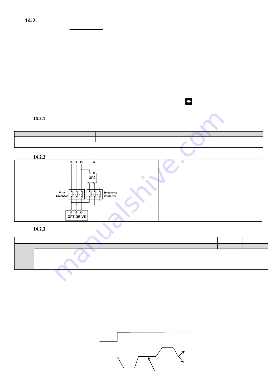
UPS Connection Diagram
Note
The Emergency Contactor can only be closed
when the Main Contactor is open.
A delay time of no less than 5 sec’s must be
included when changing over to/from UPS
supply to/From mains supply mode.
The Main Contactor and Emergency Contactor
must be interlocked so that both cannot be
energised at the same time, failure to do so
may result in damage to the UPS, contactor.
Rescue Mode speed control
Par
Parameter Name
Minimum
Maximum
Default
Units
P3-12
Rescue Operation Function
0
3
0
-
0: Basic Rescue mode
1: Light Load Detection
2: Reserved – Do Not use.
3: UPS Easiest direction based on load measurement
P3-12 = 0 (Basic rescue mode)
The Speed is defined by the rescue mode speed parameter P2-05 (Limited internally to 10Hz to prevent nuisance Under Voltage
(“
”) trips due to excess power draw/voltage drop from the UPS at higher speeds).
Travel Direction is governed by the direction command given to the drive.
P3-12= 1 (Light Load detection)
The Speed during the light load test is defined by the rescue mode speed parameter P2-05 (Default 5.0Hz).
Travel direction is decided by the light load detection test result and not the direction input, the test measures which direction is the
easiest direction in order to provide longevity of the UPS and ensure a floor is reached before the UPS is exhausted.
The light detection always starts in the downward direction (motor anti-clockwise with sheave facing you).
Direction command
Motor Speed (light direction learning)
Note: Brake is applied between direction changes.
Run in easiest direction


