background image

SECTION 2—SAFETY/HANDLING OF WHEELCHAIRS

Part No. 1110558

15

Tracer

®

 IV

Tipping


WARNING

DO NOT tip the wheelchair without assistance.

When


tipping


the


wheelchair,


an


assistant


should


grasp


the


back


of


the


wheelchair


on


a


non

removable


(non

detachable)


part.


Inform


the


wheelchair


occupant


before


tipping


the


wheelchair


and


remind


him/her


to


lean


back.


Be


sure


the


occupant’s


feet


and


hands


are


clear


of


all


wheels


and/or


pinch


points.

After


mastering


the


techniques


of


tipping


the


wheelchair,


use


one


of


the


following


methods


to


tackle


curbs,


short


stairs,


etc.

DO


NOT


allow


the


user


to


leave


the


wheelchair


while


the


seat


is


tilted.


ALWAYS


return


the


seat


to


upright


position


when


transferring


the


user


in


or


out


of


the


wheelchair.

Method 1 - Wheelchair With Step Tubes

NOTE:


For


this


procedure,


refer


to


FIGURE 2.3.

Place


foot


on


the


step


tube


and


begin


to


tilt


the


wheelchair


toward


you.


Apply


a


continuous


downward


motion


until


the


balance


point


is


achieved


and


the


front


casters


clear


the


curb.


At


this


point,


the


assistant


will


feel


a


difference


in


the


weight


distribution.


WARNING

When lowering the front casters of the 

wheelchair, DO NOT let the wheelchair 

drop the last few inches to the ground. 

This could result in injury to the occu-

pant and/or damage to the wheelchair.

Roll


the


wheelchair


forward


and


slowly


lower


the


front


of


the


wheelchair


in


one


continuous


movement


onto


the


sidewalk.


Push


the


wheelchair


forward


until


the


rear


wheels


roll


up


and


over


the


curb.

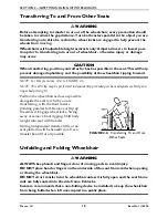
FIGURE 2.3   

Method 1 - Wheelchair With 

Step Tubes

Method 2 - Wheelchair Without Step Tubes


WARNING

ALWAYS check hand grips for looseness before using the wheelchair. If loose 

and/or worn, replace IMMEDIATELY.

Step Tube

Содержание Tracer IV

Страница 1: ...nual MUST be given to the user of the product USER BEFORE using this product read this manual and save for future reference For more information regarding Invacare products parts and services please v...

Страница 2: ...OR INSTRUCTION SHEETS SUPPLIED WITH THIS PRODUCT OR OPTIONAL EQUIPMENT IF YOU ARE UNABLE TO UNDERSTAND THE WARNINGS CAUTIONS OR INSTRUCTIONS CONTACT A HEALTHCARE PROFESSIONAL DEALER OR TECHNICAL PERSO...

Страница 3: ...e to Wheelchair Assistants 13 Reaching Leaning and Bending Forward 14 Reaching and Leaning Backwards 14 Tipping 15 Method 1 Wheelchair With Step Tubes 15 Method 2 Wheelchair Without Step Tubes 15 Stai...

Страница 4: ...Replacing Back Upholstery 34 Replacing Seat Upholstery 34 Adjusting the Seat Width 35 SECTION 7 REAR WHEELS 37 Removing Installing Rear Wheels 37 Replacing Rear Wheel Handrim 38 Replacing Repairing Re...

Страница 5: ...OUR PRODUCT The benefits of registering include 1 Safeguarding your investment 2 Ensuring long term maintenance and servicing of your product 3 Receiving updates with product information maintenance t...

Страница 6: ...made available by the auto industry Invacare cannot and does not recommend any wheelchair transportation systems SEAT POSITIONING STRAP ALWAYS wear your seat positioning strap Inasmuch as the seat po...

Страница 7: ...unting bracket and frame 2 Slide clamp toward rear wheel until wheel lock shoe is embedded into tire material at least 1 8 when handle is engaged to the lock position 3 16 for pneumatic tires 3 Tighte...

Страница 8: ...8 and 20 inches SEAT TO FLOOR 19 inches Adult 17 inches Hemi BACK STYLE Fixed BACK HEIGHT 16 inches ARM STYLES Fixed or Adjustable Height Desk or Full Length Removable FRONT RIGGINGS Swingaway Removab...

Страница 9: ...ualified technician Weight Training Invacare does not recommend the use of its wheelchairs as a weight training apparatus Invacare wheelchairs have not been designed or tested as a seat for any kind o...

Страница 10: ...attaching hardware is tightened securely otherwise injury or damage may result Unless otherwise noted all service and adjustment should be performed while the wheelchair is unoccupied To determine an...

Страница 11: ...to and from the wheelchair ALWAYS engage both wheel locks DO NOT attempt to lift the wheelchair by any removable detachable parts Lifting by means of any removable detachable parts of the wheelchair m...

Страница 12: ...heeded Techniques in this manual are a starting point for the new wheelchair user and assistant with safety as the most important consideration for all Stability and Balance WARNING ALWAYS wear your...

Страница 13: ...istants When assistance to the wheelchair user is required remember to use good body mechanics Keep your back straight and bend your knees whenever tipping the wheelchair or traversing curbs or other...

Страница 14: ...o maintain stability and balance Reaching Leaning and Bending Forward WARNING DO NOT attempt to reach objects if you have to move forward in the seat or pick them up from the floor by reaching down be...

Страница 15: ...elchair With Step Tubes NOTE For this procedure refer to FIGURE 2 3 Place foot on the step tube and begin to tilt the wheelchair toward you Apply a continuous downward motion until the balance point i...

Страница 16: ...front casters of the wheelchair DO NOT let the wheelchair drop the last few inches to the ground This could result in injury to the occupant and or damage to the wheelchair Roll the wheelchair backwa...

Страница 17: ...are facing up 2 After the wheelchair has been tilted back to the balance point one assistant in the rear backs the wheelchair up against the first step while securely grasping a non removable non det...

Страница 18: ...ormed independently provided you have adequate mobility and upper body strength Position the wheelchair as close as possible alongside the seat to which you are transferring with the front casters poi...

Страница 19: ...oth wheel locks open the footrest legrest for clearance and transfer into the wheelchair Refer to Transferring To and From Other Seats on page 18 FIGURE 2 7 Unfolding Folding Wheelchair NOTE For this...

Страница 20: ...olstery to hang between the cross braces 4 Continue to close the wheelchair by grasping the back cane furthest from you and pulling the armrest toward you FIGURE 2 8 Folding Wheelchair NOTE If the whe...

Страница 21: ...sbraces Inspect for rough sharp edges on frame and crossbraces Inspect for bent frame or crossbraces Check that the wheel locks DO NOT interfere with tires when rolling Check that the wheel lock pivot...

Страница 22: ...armrests Check that all labels are present and legible Replace if necessary Inspect Adjust Weekly Inspect tires for flat spots and wear Check pneumatic tires for proper inflation Inspect rear wheels...

Страница 23: ...nsure that the casters are free of debris Check that wheel locks are easy to engage Inspect seat and backs for rips and sagging Check that there is no excessive side movement or binding in the rear wh...

Страница 24: ...ician if damaged NOTE Tire wear is excessive if Pneumatic Tires there is missing tread or the tires are bald Urethane Tires there are cuts surface defects or the tires are loose on the rims Rubber Tir...

Страница 25: ...d be checked monthly for wear looseness deterioration Clean if desired Replace if looseness or deterioration is found 7 Check upholstery for sagging rips or tears 8 Replace any labels that are missing...

Страница 26: ...on the wheelchair frame 3 Push the front rigging assembly towards the inside of the wheelchair until it locks into place NOTE The footplate will be on the inside of the wheelchair when locked in plac...

Страница 27: ...ont rigging support 5 Rotate cam lock lever down to locked position 6 Repeat this procedure for the other footplate if necessary FIGURE 4 2 Spring Button Height 7 Reinstall the swingaway front rigging...

Страница 28: ...n lbs 9 Rotate cam lock lever down to locked position 10 Repeat STEPS 1 9 to adjust the remaining footrest FIGURE 4 3 Bolt In Place Height Raising Lowering Elevating Legrest Assembly WARNING Ensure ha...

Страница 29: ...e lever downward with other hand C Gently lower user leg down and rest against the legrest FIGURE 4 4 Raising Lowering Elevating Legrest Assembly Installing H Strap Calf Strap NOTE For this procedure...

Страница 30: ...e tube 5 Install new heel loop onto slide tube 6 Install the mounting screw spacer and locknut to secure the heel loop to the footplate Tighten until the spacer is secure 7 Insert the lower footrest a...

Страница 31: ...ETAIL A Footplates with Spring Buttons Bolt in Place Footplates Inside of Swingaway Front Rigging Outside of Swingaway Front Rigging Footplate Assembly Adjustment Hole Cam Lock Lever Footplate Assembl...

Страница 32: ...ipping the height adjustment lever on the top front of the armrest to the up horizontal position 2 Adjust armrest to one of five positions NOTE Height adjustment lever MUST be in the unlocked position...

Страница 33: ...m the arm sockets by pulling straight up Installing Armrest NOTE Rear armrest release lever MUST be in the unlocked position when installing the armrest 1 Position the armrest just above the front and...

Страница 34: ...IGURE 6 1 Replacing Back Upholstery Replacing Seat Upholstery NOTE For this procedure refer to FIGURE 6 2 1 Perform one of the following 18 Inch Deep Seats Remove the ten mounting screws and washers t...

Страница 35: ...screws and locknuts for assembling the new crossbraces 5 Assemble the two new crossbraces together with the existing two hex screws and locknuts Securely tighten Refer to FIGURE 6 3 for hardware orie...

Страница 36: ...ACK Tracer IV 36 Part No 1110558 FIGURE 6 3 Adjusting the Seat Width Crossbrace Bottom Locknuts Button Screw Crossbrace Saddles Wheelchair Frame Pivot Link Button Screws Locknut For Pivot Link Locknut...

Страница 37: ...ng the wheelchair Otherwise injury may occur For heavy duty wheel option 450 lb weight limit 24 inch pneumatic flat free insert rear wheels MUST be used NOTE For this procedure refer to FIGURE 7 1 1 R...

Страница 38: ...e handrim to the rear wheel 3 Remove the existing handrim 4 Install the new handrim by reversing STEPS 1 3 5 Reinstall rear wheel to the wheelchair Refer to Removing Installing Rear Wheels on page 37...

Страница 39: ...secure the fork to the caster headtube 3 Drop the fork assembly out of the caster headtube 4 Remove the existing fork stem washer from the existing fork assembly NOTE If caster replacement is desired...

Страница 40: ...STEPS 1 2 until correct 4 Snap dust cover over the locknut and stem Replacing Front Casters WARNING Only 8 inch casters should be installed on the Tracer IV wheelchair Otherwise the wheelchair may be...

Страница 41: ...pairing Front Caster Tire Tube WARNING Replacement of front caster tire MUST be performed by a qualified technician CAUTION As with any vehicle check the wheels and tires periodically for cracks and w...

Страница 42: ...ppers MUST be attached at all times Inasmuch as the anti tippers are an option for this wheelchair You may order with or without the anti tippers Invacare strongly recommends ordering the anti tippers...

Страница 43: ...page 43 Adjusting the Anti Tippers NOTE For this procedure refer to FIGURE 9 2 on page 44 NOTE A 1 to 2 inch clearance between the bottom of the anti tipper wheels and the ground floor MUST be mainta...

Страница 44: ...s Using Adjusting Patient Operated Wheel Locks Using Patient Operated Wheel Locks WARNING DO NOT attempt to stop a moving wheelchair with wheel locks Wheel locks are not brakes NOTE For this procedure...

Страница 45: ...when engaged the wheel lock shoe embeds the tire 1 8 inch 3 16 inch for pneumatic tires and holds the wheelchair 4 Securely tighten the bolt and locknut securing the wheel lock to the wheelchair fram...

Страница 46: ...ing Patient Operated Wheel Locks Installing Wheel Lock Shoe Extensions NOTE For this procedure refer to FIGURE 9 5 1 Loosen the two set screws on the wheel lock shoe extension until the set screws DO...

Страница 47: ...MUST be performed by a qualified technician If changing the seat to floor height the anti tippers MUST be adjusted to maintain a 1 to 2 inch ground clearance NOTE For this procedure refer to FIGURE 1...

Страница 48: ...Seat to Floor Height SEAT TO FLOOR HEIGHT IN INCHES FRONT CASTER MOUNTING POSITION REAR WHEEL SIZE REAR WHEEL MOUNTING POSITION 17 Top 24 inch Top 19 Bottom 24 inch Bottom DETAIL A REAR WHEEL MOUNTING...

Страница 49: ...desired height 3 Center pouch against back canes determine and mark location for mounting holes on carrying pouch straps 4 Punch holes in straps 5 Fold excess strap ends under mark mounting holes in...

Страница 50: ...er the end of the step tube of the wheelchair Ensure the base is towards the inside of the wheelchair 2 Position the base parallel to the step tube CAUTION Base should be parallel to step tube to avoi...

Страница 51: ...standing high stress loads such as auto or aircraft safety belts If signs of wear appear belt MUST be replaced IMMEDIATELY NOTE For this procedure refer to FIGURE 11 3 1 Remove the bottom back upholst...

Страница 52: ...oduct model number date of purchase indicate nature of the defect and if the product is serialized indicate the serial number Do not return products to our factory without our prior consent LIMITATION...

Отзывы: