


Invacare
®
- STORM
4
MAX
SERVICE MANUAL
47
8.2.4
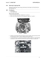
Replacing the lighting PCB
Replacement is described in the following section based on the example of a mobility aid with an
optional lighting PCB.
Requirements:
•
4 mm Allen key
•
8 mm socket spanner
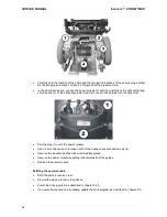
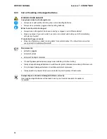
Dismantling the lighting PCB:
•
Remove the seat, as described in chapters 8.14.1 and 8.14.5.
•
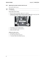
Remove the rear and the centre cover as described in chapters 8.1.1 and 8.1.2.
•
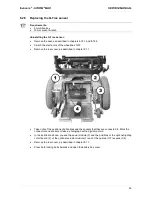
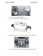
Carefully note the location of the cable and the connection locations of the various plugs. Either
mark each plug and socket, or take a photograph with a digital camera.
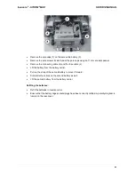
•
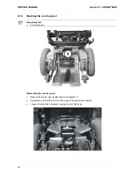
In the illustration above, you see the power module (3) and the positions of the optional lighting
circuit board (2), of the optional actuator module (1) and of the optional G-Trac sensor (4).