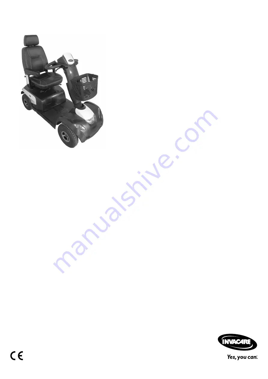
Invacare® Comet Series
CometPRO, Come, CometULTRA
en Scooter
Service Manual
DEALER: Keep this manual.The procedures in this manual MUST be performed by a qualifiedtechnician.
Страница 1: ...Invacare Comet Series CometPRO CometALPINE CometULTRA en Scooter Service Manual DEALER Keep this manual The procedures in this manual MUST be performed by a qualified technician...
Страница 2: ...ation duplication or modification in whole or in part is prohibited without prior written permission from Invacare Trademarks are identified by and All trademarks are owned by or licensed to Invacare...
Страница 3: ...cuit Board 16 5 5 3 Replacing Potentiometer 16 5 5 4 Replacing lifter lifter controls 17 5 5 5 Replacing power module 18 5 6 Shrouds 19 5 6 1 Removing shroud 19 5 6 2 Replacing front shroud 19 5 7 Lig...
Страница 4: ...this manual The mobility device may only be maintained and overhauled by qualified personnel The minimum requirement for service technicians is suitable training such as in the cycle or orthopedic mec...
Страница 5: ...ty gloves when working on any defective or possibly defective batteries General Safety Information and Information About Fitting Removal DANGER Risk of Death Serious Injury or Damage Lighted cigarette...
Страница 6: ...e to property if the maximum speed reduction on a wheelchair with a lifter does not function correctly The wheelchair s control unit must reduce the maximum possible speed as soon as the lifter is rai...
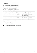
Страница 7: ...tation Manual cleaning Surface of used device Before repair or reconditioning Use saturated towel to apply cleaning detergent and remove residues after impact Cleaning and disinfection Disinfection Su...
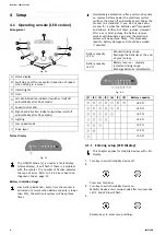
Страница 8: ...rge protection after a certain drive time on reserve battery power the electronic system switches the drive off automatically and brings the scooter to a standstill If you do not drive your scooter fo...
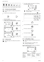
Страница 9: ...ol indication D Maintenance indication1 E Head light indication F Left turn indication G Settings shown ODO TRIP TEMP TIME H Right turn indication I Battery status J Low speed selection indication 1If...
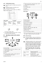
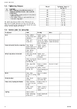
Страница 10: ...can set a km value as service interval If counter value is greater than set value symbol will flash for one minute when key is switched on 0 OFF 500 1000 1500 2000 9500 9999 max 9999 9500 9000 8500 80...
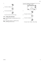
Страница 11: ...This chapter applies to mobility devices with LCD display Setting wheel diameter is mandatory when retrofitting operating console Set value according to wheel diameter 11 12 13 14 or 15 for correct d...
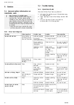
Страница 12: ...rrupted Check main fuse See user manual for main fuse position Check cable between modules for loose connections or damage See Replacing power module Status display on operating console does not illum...
Страница 13: ...Invacare provider 5 Brake failure Stops driving Ensure that the disengaging lever is in the engaged position There is a defect in the braking coil or in the cabling Check the magnetic brake and cabli...
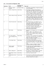
Страница 14: ...suspension Grease the spring generously replace parts if damaged See Replacing seat suspension spring Check fixings welded seams and battery mounting Frames chassis battery mounting Check battery fixi...
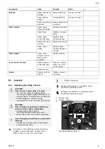
Страница 15: ...5 1 Replacing Operating Console CAUTION Risk of burns if power cable is shorted Turn off the power completely before removing any power supply components of mobility device Therefore take out batterie...
Страница 16: ...cted Areas EPA 1 Unplug battery connector 2 Remove operating console as described in chapter 5 5 1 Replacing Operating Console page 15 3 Replace circuit board 4 Make sure all pins are correctly connec...
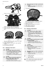
Страница 17: ...5 5 LED Fig 5 6 Reconnect potentiometer plug A with operating console 12 Connect potentiometer A and drive lever mounting B Tighten screw C 13 Install parts in reverse order 14 Test all functions tria...
Страница 18: ...f burning if power cable is shorted Turn off power completely before removing any power supply components of mobility device Therefore take out batteries Avoid bridging of contacts during measurements...
Страница 19: ...s 7 Remove rear wheels 8 Remove drive unit See 5 10 1 Replacing drive unit page 30 9 Remove screws 1 on power module 2 Rhino1 Fig 5 7 DS112KB02 DS162KD01 Rhino 2 Fig 5 8 DS120 Fig 5 9 DS160 10 Replace...
Страница 20: ...ud 3 Disconnect battery cable A 4 Remove rear steering column shroud See 5 8 4 Replacing steering column page 24 5 Remove screw A on headlight under front shroud 6 Disconnect direction indicator cable...
Страница 21: ...position of small parts such as screws and washers Put small parts down so that they can be reassembled in the right sequence Phillips screwdriver 1 Remove seat 2 Remove shroud 3 Disconnect battery ca...
Страница 22: ...ove rear light 8 Remove screws 1 on rear light glass 9 Remove rear light glass 1 10 Replace lightbulbs 2 11 Install parts in reverse order 12 Test function 5 8 Wheels 5 8 1 Replacing wheel suspension...
Страница 23: ...en disassembling note the position of small parts such as screws and washers Put small parts down so that they can be reassembled in the right sequence The drive motor needs to be removed before you c...
Страница 24: ...ear shock absorber on left and right side of mobility device Be careful not to loose metal bushing A in swing arm B 6 Remove and replace swing arm 7 Install parts in reverse order When reinstalling ti...
Страница 25: ...9 1 Replacing hand brakes page 27 14 Loosen and remove screw at clamp 1 15 Loosen and remove fixing bolt for steering column 16 Pull steering column out upwards 17 Install parts in reverse order Tight...
Страница 26: ...Loosen and remove nuts C that fix cross members to frame 11 Replace suspension 12 Install parts in reverse order Tighten screws and nuts to prescribed torque See Tightening torques page 26 13 Test all...
Страница 27: ...tube has been repaired and is to be used again and became wet during repair it is easier to replace it if it is lightly dusted with talcum powder beforehand 6 Refit wheel rim parts from outside into...
Страница 28: ...ut small parts down so that they can be reassembled in right sequence You do not need to remove wheel to replace brake cable 10 mm wrench Phillips screwdriver 1 Slacken brake cable using setting screw...
Страница 29: ...order 4 Test all functions trial run 5 9 4 Replacing curve control device CAUTION Risk of accident Accidental rolling can lead to accidents Secure mobility device against rolling away When disassembli...
Страница 30: ...rol Place mobility device rear frame on a supporting wooden block before you remove wheels CAUTION Risk of accident Accidental rolling can lead to accidents Secure mobility device against rolling away...
Страница 31: ...ut of holder and take it out of the frames to the side 3 Replace motor Replacing drive unit 1 Loosen and remove screw B on swing arm For replacing swing arm see 5 8 3 Replacing swing arm page 24 2 Loo...
Страница 32: ...me position from which they were taken or fit new brushes 2 Install plastic caps and tighten them firmly 3 Install drive wheels The following procedure is necessary to run carbon brushes in after repl...
Страница 33: ...including the spring 5 and the plastic end pieces 4 and 6 11 Insert seat support tube 2 into receptacle tube 1 and press down gently 12 Reposition bolt 7 nut and washers 13 Firmly tighten securing bol...
Страница 34: ...Crutch Cane holder Lockable storage box front Lockable storage box rear incl clutch holder bracket Rear basket Backrest bag Hour counter Rollator holder incl crutch holder Windscreen Seat belt Oxygen...
Страница 35: ...Notes...
Страница 36: ...d 4 Westfield Place Mt Wellington 1060 New Zealand Phone 0800 468 222 Fax 0800 807 788 sales invacare co nz www invacare co nz United Kingdom Invacare Limited Pencoed Technology Park Pencoed Bridgend...