background image

3G Storm Series

®

 Wheelchairs

138

Part No. 1104849

NOTES

NOTES

NOTES

Содержание 3G Storm Arrow RWD

Страница 1: ...849 1 3G Storm Series Wheelchairs Service Manual DEALER KEEP THIS MANUAL THE PROCEDURES IN THIS MANUAL MUST BE PERFORMED BY A QUALIFIED TECHNICIAN 3G Storm Series Wheelchairs Arrow RWD Torque SP RWD R...

Страница 2: ...IAL NOTES WARNING CAUTION notices as used in this manual apply to hazards or unsafe practices which could result in personal injury or property damage NOTICE THE INFORMATION CONTAINED IN THIS DOCUMENT...

Страница 3: ...TIE DOWN RESTRAINTS 16 SECTION 2 TROUBLESHOOTING 17 FIELD LOAD TEST 17 MOTOR TESTING 18 MOTOR BRUSH INSPECTION 18 ELECTRO MECHANICAL PARKING BRAKE TESTING 19 SECTION 3 HARDWARE TORQUE SPECIFICATIONS 2...

Страница 4: ...RSA 43 REMOVING INSTALLING SEAT PAN 43 SEAT ANGLE ADJUSTMENT 45 SECTION 7 BASE FRAME 46 REPLACING SEAT MOUNTING PLATES 46 REPLACING SEAT SUPPORT BRACKETS 47 REPLACING SEAT SUPPORT BRACKET T NUTS 48 RE...

Страница 5: ...1 SECTION 14 RECLINER 109 POSITIONING LIMIT SWITCH 109 ADJUSTING LIMIT SWITCH 110 REPLACING RECLINER CABLE ASSEMBLIES 111 REPLACING ADJUSTING GAS CYLINDERS 113 CHANGING BACK HEIGHT 114 CHANGING SEAT D...

Страница 6: ...WIDTH OF BASE w o joystick 25 inches Overall Height Standard 34 inches Minimum 34 inches Maximum 44 inches Recliner Low Seat Frame 51 inches Med Seat Frame 53 inches High Seat Frame 55 inches OVERALL...

Страница 7: ...ARMRESTS Flip Back Fixed or Adjustable Height Desk and Full Length SEAT ANGLE ADJUSTMENT Adjustable 0o to 10o SEAT CUSHION Cushion Optional CHAIR UPHOLSTERY OPTIONS Nylon BATTERY REQUIREMENTS See cha...

Страница 8: ...34 inches Maximum 44 inches Recliner Low Seat Frame 51 inches Med Seat Frame 53 inches High Seat Frame 55 inches OVERALL LENGTH without front riggings Standard 29 inches Long Frame 32 inches WEIGHT MO...

Страница 9: ...e Height Desk and Full Length SEAT ANGLE ADJUSTMENT Adjustable 0o to 10o SEAT CUSHION Cushion Optional CHAIR UPHOLSTERY OPTIONS Naugahyde and Nylon BATTERY REQUIREMENTS See chart on page 70 PERFORMANC...

Страница 10: ...w o joystick 25 inches Overall Height Standard 34 inches Minimum 34 inches Maximum 44 inches Recliner Low Seat Frame 51 inches Med Seat Frame 53 inches High Seat Frame 55 inches OVERALL LENGTH without...

Страница 11: ...ont Rigging Supports Swing Away Std Heavy Duty Opt 4 in longer Pivot Slide Tube Opt ARMRESTS Flip Back Fixed or Adjustable Height Desk and Full Length SEAT ANGLE ADJUSTMENT Adjustable 0o to 10o SEAT C...

Страница 12: ...re that the wheelchair performs to the specifications entered during the setup procedure If the wheelchair does NOT perform to specifications turn the wheelchair OFF immediately and reenter setup spec...

Страница 13: ...pting active use of the wheelchair DO NOT attempt to reach objects if you have to move forward in your seat DO NOT attempt to reach objects if you have pick them up from the floor by reaching between...

Страница 14: ...attempt to lift the wheelchair by any removable detachable parts Lifting by means of any removable detachable parts of a wheelchair may result in injury to the user or damage to the wheelchair DO NOT...

Страница 15: ...ressure P S I DO NOT overinflate the tires A qualified technician MUST perform replacement of a pneumatic tire or tube Failure to follow these warnings may cause the tire to explode and cause bodily h...

Страница 16: ...NSION ARM USED WITH CONVENTIONAL MOTOR GEARBOX ASSEMBLY Invacare recommends that wheelchair users NOT be transported in vehicles of any kind while in wheelchairs As of this date the Department of Tran...

Страница 17: ...e instructions CAREFULLY before using the digital voltmeter NOTE Invacare recommends that ONLY qualified service personnel perform this test 1 Ensure that power is OFF 2 Make sure battery is fully cha...

Страница 18: ...ms indicates a problem High readings are generally caused by bad connections and or damaged brushes Contact authorized dealer or Invacare MOTOR BRUSH INSPECTION FIGURE 3 NOTE This procedure should onl...

Страница 19: ...ANICAL PARKING BRAKE TESTING FIGURE 4 NOTE This procedure should only be performed on wheelchairs with conventional motor gearbox assembly 1 On the four pin motor connector locate the side by side con...

Страница 20: ...156 in lbs Torque to 156 in lbs Torque to 156 in lbs HARDWARE TORQUE SPECIFICATIONS STANDARD SEAT FRAME NOTE These torque specifications also apply to the ASBA assembly These torque specifications al...

Страница 21: ...VAN SEAT Loctite and Torque to 75 in lbs Torque to 156 in lbs Torque to 156 in lbs NOTE For additional torque specifications refer to the torque specifications drawing for the standard seat frame ass...

Страница 22: ...DJUSTABLE SEAT BACK ANGLE Torque to 156 in lbs Torque to 156 in lbs Torque to 156 in lbs Torque to 156 in lbs NOTE For additional torque specifications refer to the torque specifications drawing for t...

Страница 23: ...e to 156 in lbs Torque to 156 in lbs Torque to 156 in lbs and back off 1 4 turn Loctite and torque to 75 in lbs Wheel Halves 8 inch Torque to 18 in lbs 9 inch Torque to 156 in lbs Loctite and Torque t...

Страница 24: ...in lbs Torque to 75 in lbs NOTE All torque specifications called out for the conventional motor gearbox assembly are applicable to the gearless brushless motor except for the specs called out below To...

Страница 25: ...PADS FIGURE 1 1 Remove the locknut and washer from the outside of the armrest pad 2 Remove the mounting screw securing the armrest pad to the armrest post 3 Position the new armrest pad so the mounti...

Страница 26: ...ING REMOVING VAN SEAT ASSEMBLY in SECTION 6 of this manual 2 Remove the two 2 rear mounting screws washers and locknuts that secure the seat positioning straps to the van seat frame NOTE The washer is...

Страница 27: ...hrough the cane from the inside of the wheelchair to hold the insert in place 6 Remove the other mounting screw washer spacer and locknut that secures the back cane to the seat frame 7 Slide the back...

Страница 28: ...RY POSITIONING STRAP SECTION 5 FIGURE 2 REPLACING BACK UPHOLSTERY Locknut Mounting Screw Torque to 60 in lbs Spreader Bar Mounting Screw Washer Back Upholstery Back Cane Insert Mounting Screws Torque...

Страница 29: ...WARNING After ANY adjustments repair or service and BEFORE use make sure that all attaching hardware is tightened securely otherwise injury or damage may result NOTE The procedures in this section of...

Страница 30: ...the manual 8 Disconnect battery and left right motor connectors from the controller Refer to REMOVING INSTALLING WIRING HARNESS in SECTION 10 of this manual 9 Remove tie wraps that secures the wiring...

Страница 31: ...outlined in PREPARATION FOR REMOVING INSTALLING SEAT FRAME STANDARD FRAME ADJUSTABLE FRAME AND VAN SEAT in this section of the manual REMOVING INSTALLING STANDARD SEAT FRAME SUBASSEMBLY FIGURE 2 REMOV...

Страница 32: ...one 1 of the following A If the current seat depth and the desired seat depth is within the 12 to 15 inch seat depth range this change can be accomplished by repositioning the back canes on the CJ bac...

Страница 33: ...ge requires a new side frame and or new center frame perform the following steps A Perform the instructions outlined in SEAT FRAME REMOVING INSTALLING PREPARATION FOR STANDARD FRAME ASBA AND VAN SEAT...

Страница 34: ...crews and locknuts Torque to 156 in lbs H Secure NEW side frame to the center frame at the position noted previously Torque to 75 in lbs NOTE If seat width adjustment is also desired refer to CHANGING...

Страница 35: ...g screw washer and coved washer from the top mounting hole of the CJ back bracket and back cane NOTE Before removing the back canes from the CJ back brackets note the BACK ANGLE for reinstallation NOT...

Страница 36: ...RACKETS in SECTION 8 of this manual 4 Reinstall the components previously removed in STEP 1 Perform the instructions outlined in PREPARATION FOR REMOVING INSTALLING SEAT FRAME STANDARD FRAME ADJUSTABL...

Страница 37: ...A AND VAN SEAT in this section of the manual NOTE When performing the steps outlined in PREPARATION FOR REMOVING INSTALLING SEAT FRAME STANDARD FRAME ASBA AND VAN SEAT the seat pan seat cushion back u...

Страница 38: ...support brackets to the seat mounting plates with four 4 mounting screws and locknuts Torque mounting screws to 156 in lbs 2 Secure the center frame to the support brackets with four 4 mounting screw...

Страница 39: ...nstall new existing side frame s into new existing center frame at the mounting position previously noted Torque to 75 in lbs 7 Perform the instructions outlined in PREPARATION FOR REMOVING INSTALLING...

Страница 40: ...emove van seat from seat mounting plates REPLACING VAN SEAT AND OR VAN SEAT FRAME FIGURE 8 1 Perform the instructions outlined in PREPARATION FOR REMOVING INSTALLING SEAT FRAME STANDARD FRAME ADJUSTAB...

Страница 41: ...ASBA SUBASSEMBLY AND OR COMPONENT REPLACEMENT in this section of the manual 4 ASBA ONLY Adjust side frame to desired seat width Refer to CHANGING SEAT WIDTH in this section of the manual for mounting...

Страница 42: ...nual B Adjust side frames to desired seat width Refer to CHANGING SEAT WIDTH in this section of the manual for mounting hole locations and allowable seat width seat depth combinations C 12 TO 15 INCH...

Страница 43: ...l 4 STANDARD FRAMES ONLY ON 12 TO 15 INCH SEAT DEPTHS ONLY Install the CJ back brackets from the onto the ASBA Refer to REMOVING INSTALLING CJ BACK BRACKETS in SECTION 8 of this manual 5 Perform the i...

Страница 44: ...2 inches wide and 23 to 24 inches wide 3 Reinstall the remaining mounting screws locknuts and spacers Torque all mounting screws to 75 in lbs 4 Remove the protective strips from new seat pan and reins...

Страница 45: ...that secures the seat mount plate to the seat support bracket B Loosen the two 2 mounting screws that secures the remaining seat mount plate to the seat support bracket C Adjust the seat mount plates...

Страница 46: ...INSTALLING STANDARD SEAT FRAME SUBASSEMBLY in SECTION 6 of this manual B Remove ASBA subassembly Refer to INSTALLING REMOVING ASBA ASSEMBLY AND OR COMPONENT REPLACEMENT in SECTION 6 of this manual C...

Страница 47: ...acket in this procedure If an adjustment is desired refer to ADJUSTING WEIGHT DISTRIBUTION in SECTION 15 of this manual 4 Remove the two 2 mounting screws and washers that secure the seat support brac...

Страница 48: ...CTION 6 of this manual 2 Perform one 1 of the following A Remove standard seat frame subassembly Refer to REMOVING INSTALLING STANDARD SEAT FRAME SUBASSEMBLY in SECTION 6 of this manual B Remove ASBA...

Страница 49: ...Refer to REPLACING SEAT SUPPORT BRACKETS in this section of the manual 12 Reinstall the seat mount plates Refer to REPLACING SEAT MOUNTING PLATES in this section of the manual 13 Adjust seat mounting...

Страница 50: ...AT FRAME STANDARD FRAME ASBA AND VAN SEAT in SECTION 6 of this manual REMOVING INSTALLING SEAT STOP SCREWS FIGURE 5 NOTE The front seat stop screw should only be removed if replacing a T nut for eithe...

Страница 51: ...back bracket 5 Repeat STEPS 2 4 for the opposite CJ back bracket 6 For replacement of CJ back brackets proceed to INSTALLING CJ BACK BRACK ETS in this section of the manual INSTALLING CJ BACK BRACKETS...

Страница 52: ...he threaded studs of the CJ back bracket Torque to 75 in lbs 6 For replacing CJ back brackets only perform the instructions outlined in PREPARATION FOR REMOVING INSTALLING SEAT FRAME STANDARD FRAME AD...

Страница 53: ...isting back canes 5 Remove the back assembly from the wheelchair 6 If applicable loosen but do not remove the mounting screws and locknuts that secure the spreader bar to the existing back canes 7 Rem...

Страница 54: ...reader Bar required on back heights 20 to 24 inches Spreader bar ONLY required on these back heights if the width or depth of the chair exceeds 19 inches Height of Spreader Bar from Bottom of Back Can...

Страница 55: ...g screw and washer from the bottom mounting hole of the back angle plate and back cane 4 Reposition the back canes into the correct mounting holes of the back angle plate to obtain a back angle betwee...

Страница 56: ...ge to your wheelchair and give you unsatisfactory performance ALWAYS use a battery lifting strap when lifting a battery It is the most convenient method and assures that the battery acid will not spil...

Страница 57: ...ROPER BATTERIES 22NF POSITIVE Battery Terminal Post NEGATIVE Battery Terminal Post WARNING FOR 3G STORM WHEELCHAIRS THAT USE 22NF BATTERIES Batteries with terminal configuration positive on the left a...

Страница 58: ...ion positive on the right and negative on the left as shown below MUST be used Batteries that have the reverse terminal configuration MUST not be used otherwise injury and damage may occur Terminals m...

Страница 59: ...oup 24 Batteries B 22NF batteries in single battery box 3 Secure battery lifting strap to battery terminal s post s FIGURE 3 CAUTION Some battery manufacturers mold a carrying strap and or hold down f...

Страница 60: ...battery box 1 Lift up on battery box lid to expose underlying cables 2 Peel back battery clamp covers to expose battery clamp on each battery cable as follows A RED battery clamp cover from RED batter...

Страница 61: ...ERY CABLE S GROUP 24 BATTERIES ONE 1 CONNECTOR BATTERY BOX BLACK Battery Clamp Cover RED Battery Clamp Cover Red POSITIVE Battery Cable Clamp Black NEGATIVE Battery Cable Clamp Black NEGATIVE Battery...

Страница 62: ...tery box top above battery as shown in FIGURE 5 2 Peel back battery terminal caps to expose battery cable ends as follows A RED battery terminal cap from RED battery cable B BLACK battery terminal cap...

Страница 63: ...k NEGATIVE Battery Cable One 1 Connector Battery Box Top BLACK Battery Terminal Cap RED Battery Terminal Cap Black NEGATIVE Battery Cable RED POSITIVE Battery Cable Two 2 Connector Battery Box Top DET...

Страница 64: ...NEGATIVE N terminal end to NEGATIVE battery terminal post of front battery and connect POSITIVE P terminal end to POSITIVE battery terminal post of rear battery 3 Place battery top upside down on top...

Страница 65: ...ttery Terminal Post NOTE Battery box top cut away for clarification purposes only STEPS 3 AND 4 Battery Box Top Under Side shown NEGATIVE BLACK Battery Cable Front Battery Rear Battery Battery Box Bot...

Страница 66: ...F Full As the battery becomes discharged the farthest right segments will progressively disappear a half bar at a time until no segments appear between E and F At this level the word RECHARGE will app...

Страница 67: ...time to charge a battery is called the charge rate If due to usage the charge stored in the battery is low the charge rate is high as indicated by the green light on the charger Initially the green l...

Страница 68: ...can be positioned on either side of the wheelchair for user convenience NOTE FOR RECLINERS ONLY If the wheelchair is a recliner the battery charger connector as well as the limit switch are factory se...

Страница 69: ...battery sizes are deep cycle batteries NOTE Charge batteries daily It is critical not to let them run low at any time 1 Remove the battery boxes from the wheelchair Refer to REMOVING INSTALLING BATTER...

Страница 70: ...rushless Group 24 Up to 400 lbs 4 Pole Motor Group 24 TORQUE SP Up to 250 lbs 4 Pole Motor 22NF 251 300 lbs 4 Pole Motor 22NF Gearless Brushless Group 24 301 350 lbs 4 Pole Motor Group 24 RANGER X Up...

Страница 71: ...areas should be shiny not dull 4 Carefully dust off all metal particles REMOVING INSTALLING BATTERY BOXES GROUP 24 BATTERY BOXES FOR WHEELCHAIRS WITHOUT VENT TRAY FIGURE 8 WARNING Each battery weighs...

Страница 72: ...ng the connector on the one 1 battery box lid 6 Secure the battery box carrying strap to the lid of the one 1 connector battery box 7 Place one 1 connector battery box onto battery sub frame 8 Slide o...

Страница 73: ...Secure the battery box carrying strap to the lid of the two 2 connector battery box 4 Place two 2 connector battery box onto the battery sub frame assembly with guide pins facing the inside of the whe...

Страница 74: ...s securely clipped locked into place 22NF BATTERY BOXES FIGURE 10 NOTE To install the battery box onto the wheelchair reverse the following procedure 1 Place the wheelchair in a well ventilated area w...

Страница 75: ...EELCHAIRS WITH GEARLESS BRUSHLESS MOTOR A Cut TIE WRAP A that secures the battery charger cable to the base frame DETAIL C of FIGURE 1 NOTE For STEPS 4 6 refer to DETAIL B or C of FIGURE 1 4 Disconnec...

Страница 76: ...GEARLESS BRUSHLESS MOTOR WIRING HARNESS WHEELCHAIRS WITH GEARLESS BRUSHLESS MOTOR OPTION A Secures the battery charger cable to the base frame with TIE WRAP A DETAIL C 5 Reinstall the battery boxes R...

Страница 77: ...rom the controller connector BLUE 5 Remove the two mounting screws that secure the charger cable to the mounting bracket 6 Remove the wiring harness Installing 1 Secure the charger cable to the mounti...

Страница 78: ...r of the seat frame in the same manner for wheelchairs with conventional motor gearbox assembly Joystick Cable Wiring Harness Tie Wraps A and B Motor Connector Controller Connector Mounting Screws Bat...

Страница 79: ...back angle is adjusted to 114 o relative to the seat it will measure 61 o relative to the ground NOTE To determine 114 o back angle relative to the seat frame place a magnetic protractor available at...

Страница 80: ...r CAUTION DO NOT over tighten the phillips screws that secure the actuator to the upper limit switch bracket Damage to the actuator can occur D Only tighten the two 2 phillips screws washers and lockn...

Страница 81: ...42 and torque to 160 in lbs 4 Reinstall the mounting screw that secures the retainer clip and shock or rubber element to the base frame Use Loctite 242 and torque to 160 in lbs 5 Reinstall the battery...

Страница 82: ...1104849 Retainer Clip Mounting Screws Battery Box Sub frame Base Frame Retainer Bar Shock Assembly Spacer SECTION 11 FIGURE 1 REPLACING BATTERY BOX RETAINER BAR RETAINER CLIP RETENTION STRAP RETAINER...

Страница 83: ...CAUTION As with any vehicle the wheels and tires should be checked periodically for cracks and wear and should be replaced REPLACING PNEUMATIC TIRES TUBES DRIVE WHEELS CASTERS WARNING DO NOT use your...

Страница 84: ...hex nuts to 160 inch pounds 2 Repeat procedure for opposite side of wheelchair if necessary 3 Reinstall the battery boxes Refer to REMOVING INSTALLING BATTERY BOXES in SECTION 9 of this manual WHEELS...

Страница 85: ...inch in length can cause the anti seize compound to leak resulting in damage to flooring carpet tile etc 2 Apply a thin film of anti seize compound 1 inch in length to the end of the drive shaft 3 Rei...

Страница 86: ...er GB Motor Four 4 Locknuts FIGURE 3 REMOVING INSTALLING GB MOTOR SPACER REMOVING INSTALLING THE ADAPTER PLATE WITH STUDS FIGURE 4 REMOVING 1 Remove the drive wheel from the wheelchair Refer to REMOVI...

Страница 87: ...m 2 Line up mounting holes in the wheel lock mounting bracket with the gearbox mounting holes in the suspension arm 3 Apply Loctite 242 to the two 2 mounting screws 4 Reinstall the two 2 mounting scre...

Страница 88: ...m and tire from the gearless brushless motor INSTALLING 1 Perform one 1 of the following A Pneumatic Tires Secure new existing rim and new existing pneumatic tire w new tube if applicable to the gearl...

Страница 89: ...neumatic tires inflate tire to proper tire pressure located on the side wall of the tire REMOVING INSTALLING CASTERS FIGURE 7 WARNING DO NOT use your power wheelchair unless it has the proper tire pre...

Страница 90: ...Improper positioning of the washer will prohibit the free movement of the forks 8 Install the caster onto the new fork Refer to REMOVING INSTALLING CASTERS in this section of the manual 9 Adjust the f...

Страница 91: ...nserting coupling drive plate onto slot on shaft C Carefully align motor and coupling and place motor against gearbox D With motor against gearbox turn gearbox drive shaft until the coupler seats into...

Страница 92: ...screws and washers that secure the motor to the suspension arm 11 Remove motor with motor lock lever from suspension arm 12 If replacing motor remove the motor lock lever from the brake release shaft...

Страница 93: ...11 Install the battery boxes Refer to REMOVING INSTALLING BATTERY BOXES in SECTION 9 of this manual SECTION 12 WHEELS MOTORS Mounting Screw Washer Mounting Screws Mounting Screws Washer Motor Suspensi...

Страница 94: ...ecure the gearless brushless motor and spacer motor to the suspension arm 10 Remove the gearless brushless motor and fender bracket from the suspension arm SECTION 12 WHEELS MOTORS WHEELS MOTORS Insta...

Страница 95: ...LING THE MOTOR HEAVY DUTY GEARLESS BRUSHLESS MOTOR Upper Mounting Screws Washers Gearless Brushless Motor Suspension Arm Cotter Pin Lower Mounting Screws Motor Lock Lever Gearless Brushless Fender Bra...

Страница 96: ...the gearbox to the suspension arm otherwise damage to the gearbox casting can result 4 Secure the rear of 4 pole fender bracket to the suspension arm and motor gearbox in the orientation shown using...

Страница 97: ...ecures the rear of motor gearbox to the suspension arm CAUTION The longer mounting screws MUST be used to secure the REAR of the gearbox to the suspension arm and the SHORTER mounting screws MUST be u...

Страница 98: ...lbs 4 Secure the fender and spacer to the gearless brushless fender bracket in the orien tation shown with the two 2 pan head tap screws provided Securely tighten 5 Reinstall the drive wheel Refer to...

Страница 99: ...screws to 160 in lbs 4 Secure the fender and spacer to the fender bracket in the orientation shown with the two 2 pan head tap screws provided Securely tighten 5 Reinstall rim and tire to the gearles...

Страница 100: ...rear of the armrest pad and armrest insert to the armrest plate 6 Remove the armrest pad from the armrest plate 7 Remove the lug bolt washers and locknut that secure the existing armrest plate to the...

Страница 101: ...ecure the rear of the MKIV controller to the controller bracket INSTALLING MKIV CONTROLLER WHEELCHAIRS EQUIPPED WITH NON POWERED SEATING SYSTEMS FIGURE 2 1 Secure the rear of the MKIV controller to th...

Страница 102: ...NSTALLING THE MKIV CONTROLLER WHEELCHAIRS EQUIPPED WITH NON POWERED SEATING SYSTEMS 8 32 x 1 2 inch Mounting Screws 8 32 x 1 2 inch Mounting Screws Controller Bracket 5 16 18 x 1 inch Hex Head Cap Scr...

Страница 103: ...e controller bracket INSTALLING GB CONTROLLER WHEELCHAIRS EQUIPPED WITH NON POWERED SEATING SYSTEMS FIGURE 3 1 Secure the rear of the GB controller to the controller bracket with two 2 of the NEW 10 3...

Страница 104: ...OLLER WHEELCHAIRS EQUIPPED WITH NON POWERED SEATING SYSTEMS 10 32 x 1 2 inch Mounting Screw 8 32 x 1 2 inch Mounting Screws Jumper Cable Controller Bracket GB Controller 5 16 18 x 1 inch Hex Head Cap...

Страница 105: ...controller bracket INSTALLING MKIV CONTROLLER WHEELCHAIRS EQUIPPED WITH 2ND GENERATION POWERED SEATING SYSTEMS FIGURE 4 1 Secure the rear of the MKIV controller to the controller bracket with two 2 o...

Страница 106: ...Screws Controller Bracket 8 32 x 1 2 inch Mounting Screw 5 16 18 x 1 inch Hex Head Cap Screw Jumper Cable Lockwasher MKIV Controller FIGURE 4 REMOVING INSTALLING THE MKIV CONTROLLER WHEELCHAIRS EQUIP...

Страница 107: ...that secure the rear of the GB controller to the controller bracket INSTALLING GB CONTROLLER WHEELCHAIRS EQUIPPED WITH 2ND GENERATION POWERED SEATING SYSTEMS FIGURE 5 1 Secure the rear of the GB cont...

Страница 108: ...crews STEP 1 Jumper Cable 5 16 18 x 1 inch Hex Head Cap Screw Controller Bracket 10 32 x 1 2 inch Mounting Screw Lockwashers 5 16 18 x 1 inch Hex Head Cap Screw FIGURE 5 REMOVING INSTALLING THE GB CON...

Страница 109: ...onnector 1 Cut the two 2 tie wraps that secure the limit switch wire to the seat frame 2 Remove the two 2 mounting screws and washers that secure the actuator to the gas cylinder pivot block 3 Positio...

Страница 110: ...h does not stop the wheelchair from operating in a recline position greater than 105o RELATIVE TO THE SEAT FRAME do not operate the wheelchair Adjust the limit switch BEFORE using the wheelchair other...

Страница 111: ...s cylinder from the operator of the existing recliner cable assembly but do not remove the gas cylinder from the pivot block 6 Remove the operator of the existing recliner cable assembly from the pivo...

Страница 112: ...andle 11 Reinstall the mounting screw through the mounting bracket of the back cane nylon washer gas cylinder nylon washer mounting bracket and washer and securely tighten with the existing locknut To...

Страница 113: ...g hole in the operator of the recliner cable assembly with the new gas cylinder rod CAUTION DO NOT force the gas cylinder rod into the operator of the recliner cable assembly DO NOT cross thread the o...

Страница 114: ...de of the back DOES NOT recline 3 To adjust the RIGHT gas cylinder Repeat STEPS 1 and 2 for the LEFT handle of the cable assembly CAUTION Damage to the gas cylinder rod WILL occur if the following ste...

Страница 115: ...gas cylinder nylon washer mounting bracket and washer and securely tighten with the existing locknut Torque to 75 in lbs 11 Reinstall the recliner cable assemblies onto the back canes Refer to REPLAC...

Страница 116: ...an EVEN number i e 16 inches 18 inches 20 inches or 22 inches the seat depth CANNOT be DECREASED without changing the seat frame Refer to INSTALLING REPLACING ADJUSTABLE 16 TO 19 INCH DEEP RECLINER S...

Страница 117: ...SE FRAME FIGURE 7 1 Perform instructions outlined in PREPARATION FOR REMOVING INSTALLING SEAT FRAME STANDARD FRAME ADJUSTABLE FRAME AND VAN SEAT in SECTION 6 of this manual 2 Perform one 1 of the foll...

Страница 118: ...limit switch onto wheelchair Refer to POSITIONING LIMIT SWITCH in this section of the manual 7 Reinstall recliner seat pan with existing six 6 mounting screws 8 Install the two 2 warnings labels onto...

Страница 119: ...at all attaching hardware is tightened securely otherwise injury or damage may result REMOVING INSTALLING GROUP 24 BATTERY BOX SUB FRAME FIGURE 1 REMOVING 1 Remove the battery boxes Refer to REMOVINg...

Страница 120: ...THOUT VENT TRAY Reinstall the four 4 mounting screws that secure the shocks and spacers to the base frame 3 Reinstall the battery boxes Refer to REMOVING INSTALLING BATTERY BOXES in SECTION 9 of this...

Страница 121: ...n SECTION 9 of this manual RWD WHEELCHAIRS SECTION 15 CONVERTING 22NF BATTERY BOX TRAY TO GROUP 24 BATTERY BOX SUB FRAME ASSEMBLY REMOVING 22NF COMPONENTS FIGURE 3 1 Remove the battery box Refer to RE...

Страница 122: ...e following A WHEELCHAIRS EQUIPPED WITH VENT TRAY WARNING WARNING WARNING WARNING WARNING The Battery Box Retainer Retainer Clip MUST be fastened securely in place before using the wheelchair Use Loct...

Страница 123: ...VING INSTALLING BATTERY BOXES in SECTION 9 of this manual RWD WHEELCHAIRS SECTION 15 RWD WHEELCHAIRS STEPS 1 3 Wiring Harness w Bracket Mounting Screws Battery Box Sub Frame Base Frame Locknuts REAR O...

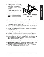
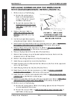
Страница 124: ...to the base frame 5 Perform one 1 of the following A FOR SHOCKS Remove the mounting screw two 2 short spacers two 2 large washers and locknut that secure the shock to the anti tip bracket and suspensi...

Страница 125: ...small washers two 2 short spacers one 1 2 inch spacer and locknut Torque to 13 ft lbs 9 Reinstall the drive wheel from the wheel hub Refer to REMOVING INSTALLING THE DRIVE WHEELS in SECTION 12 of thi...

Страница 126: ...g screw two 2 short spacers two 2 large washers and lcoknut that secure the shock to the anti tip bracket and suspension arm 5 Remove the shock from the base frame 6 Secure the top of the NEW shock to...

Страница 127: ...the spring retainer and turn the shock eyelet assembly counterclockwise to unthread it from the shock 6 Remove the spring retainer and spring 7 Place the NEW spring onto the shock 8 Reinstall the shoc...

Страница 128: ...for clarity There is no need to remove shock from suspension arm Suspension Arm Mounting Screw Shock Battery Box Retainer Bar Hex Screws Spacer Shock Eyelet Assembly Retainer Clip GROUP 24 BATTERIES...

Страница 129: ...earbox Refer to REMOVING INSTALLING THE MOTOR in SECTION 12 of this manual INSTALLING CAUTION The REAR hex screws that secure the gearbox to the suspension arm MUST be 5 16 18 x 2 1 2 inches long and...

Страница 130: ...the user Disadvantage More weight is put on front casters and makes turning more difficult NOTE This option can also be accomplished by moving the motor backward on the suspension arm Refer to REPOSI...

Страница 131: ...rom the wheelchair Refer to REMOVING INSTALLING DRIVE WHEELS in SECTION 12 of this manual 3 Remove gearbox from the suspension arm Refer to REMOVING INSTALLING GEARBOX in this section of the manual 4...

Страница 132: ...WITH WITH MANUAL RECLINER 2G POWERED SEATING SYSTEM OR HIGH BACK VAN SEAT STANDARD POSITION LENGTHENS the wheelbase and gives you the most stability and standard maneuverability 1 INCH FORWARD CENTERS...

Страница 133: ...or to the suspension arm 7 Slide the motor forward or backward to the desired mounting position 8 Secure the motor to the mounting position determined in STEP 1 and secure with the four 4 existing mou...

Страница 134: ...d mounting position for the motor Moving the motor lock lever one position forward would correrspond with the one inch forward motor mounting position 5 Reposition the motor to the desired mounting po...

Страница 135: ...he beveled washers MUST be placed on the inside and outside of the base frame with the bevels facing each other 7 Install the NEW suspension arm assembly onto the base frame 8 Torque suspension arm he...

Страница 136: ...led washers that secure the front of the suspension arm to the base frame 8 Remove the existing suspension arm from the base frame 9 Install the new suspension arm onto the base frame 10 Install mount...

Страница 137: ...x head mounting screw two 2 small spacers and locknut for installation of the 4 inch active anti tip assemblies 2 Remove the 5 16 18 x 3 1 4 inch hex head cap screw two 2 small washers long spacer and...

Страница 138: ...3G Storm Series Wheelchairs 138 Part No 1104849 NOTES NOTES NOTES...

Страница 139: ...4849 139 3G Storm Series Wheelchairs WARRANTY WARRANTY LIMITED WARRANTY For warranty information please refer to the original owner s manual which came with this product or contact Invacare for more i...

Страница 140: ...o USA Mississauga Ontario Design Storm Series and Arrow are 44036 2125 L4Z 4G4 Canada registered trademarks of Invacare 800 333 6900 800 668 5324 Corporation Ranger X Torque SP and MKIV are trademarks...

Отзывы: