
133
SAVE THESE INSTRUCTIONS
Page 12
(133) MODEL CS8111 SALTWATER SYSTEM & FILTER PUMP ENGLISH 7.5” X 10.3” PANTONE 295U 11/17/2011
English
SSEE
TTUU
PP
IINN
SSTT
RRUU
CCTT
IIOO
NNSS
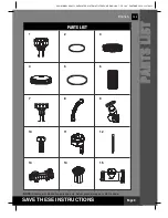
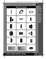
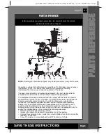
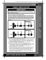
The strainer grid prevents large objects from jamming and/or damaging the
filter pump. If your pool has an inflatable top ring, install the strainer, nozzle
and plunger valve before inflating the pool liner top ring. The part numbers
here onward refer to the parts depicted in the Parts List section of this
manual. To install, do the following:
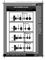
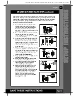
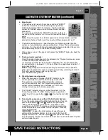
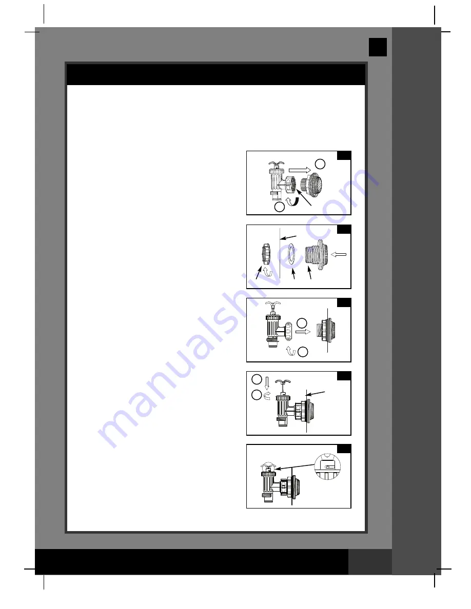
STRAINER & PLUNGER VALVE SETUP (continued)
1.
In a counter-clockwise motion unscrew
plunger valve union from the threaded
strainer connector
(24) (see drawing 1).
Be careful not to lose the step rubber
washer
(21)
. Place the plunger valve on the
ground in a safe place.
2.
In a counter-clockwise motion unscrew the
strainer nut
(22)
from the threaded
connector
(24).
Leave the flat washer
(23)
on the connector
(24)
.
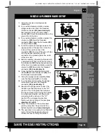
3.
Install the strainer and plunger valve at the
lower position of pool outlet (marked "+").
From the inside of the pool liner insert the
connector
(24)
into one of the pre-cut holes
with the washer remaining on the
connector to be placed against the inside
of the liner wall.
4.
Before assembly, lubricate the threads with
a petroleum jelly. Then, with the flat side of
the strainer nut
(22)
facing the outside wall
of the liner in a clockwise motion screw the
strainer nut
(22)
back onto the threaded
connector
(24) (see drawing 2)
.
5.
Finger tighten the strainer nut
(22)
onto the
threaded connector
(24)
.
6.
Grasp the plunger valve assembly. Make
sure the step washer
(21)
is in place.
7.
In a clockwise motion screw the plunger
valve union back onto the threaded
connector
(24) (see drawing 3)
.
8.
Examine the plunger valve to see if the
handle is pushed fully down to the "0/1"
position. If not, grasp the handle at
the top and push down, turning the handle
in a clockwise direction until the plastic
protruding notch anchors in the "0/1"
position. This will prevent water from
flowing out during filling of the pool
(see
drawings 4.1 & 4.2)
.
1
2
3
4.1
4.2
23
24
21
INSIDE
LINER WALL
INSIDE
LINER
WALL
22
2
1
1
2
1
2


