

2 / 2
This information is subject to change without prior notice
IntesisBox
is a registered trademark of Intesis Software S.L.U.
email:
web:
www.intesisbox.com
phone: +34 938047134
Enclosure
Plastic, type PC (UL 94 V-0)
Net dimensions (d
x
w
x
h): 90x88x56 mm
Recommended space for installation (d
x
w
x
h): 130x100x100mm
Color: Light Grey. RAL 7035
Battery
Size: Coin 20mm x 3.2mm
Capacity: 3V / 225mAh
Type: Manganese Dioxide Lithium
Mounting
Wall.
DIN rail EN60715 TH35.
Console Port
Mini Type-B USB 2.0 compliant
1500VDC isolation
Terminal Wiring
(for power supply and
low-voltage signals)
Per terminal: solid wires or stranded wires (twisted or with
ferrule)
1 core: 0.5mm
2
… 2.5mm
2
2 cores: 0.5mm
2
… 1.5mm
2
3 cores: not permitted
USB port
Type-A USB 2.0 compliant
Only for USB flash storage device
(USB pen drive)
Power consumption limited to 150mA
(HDD connection not allowed)
Power
1 x Plug-in screw terminal block (3 poles)
9 to 36VDC +/-10%, Max.: 140mA.
24VAC +/-10% 50-60Hz, Max.: 127mA
Recommended: 24VDC
Push Button
Button A: Check the user manual
Button B: Check the user manual
Operation
Temperature
0°C to +60°C
Ethernet
1 x Ethernet 10/100 Mbps RJ45
2 x Ethernet LED: port link and activity
Operational
Humidity
5 to 95%, no condensation
Port A
1 x Serial EIA485 Plug-in screw terminal block (2 poles)
A, B
1 x Plug-in screw terminal block green (2 poles)
SGND (Reference ground or shield)
1500VDC isolation from others ports
Protection
IP20 (IEC60529)
LED
Indicators
10 x Onboard LED indicators
2 x Run (Power)/Error
2 x Ethernet Link/Speed
2 x Port A TX/RX
2 x Port B TX/RX
1 x Button A indicator
1 x Button B indicator
Switch A
(SWA)
1 x DIP-Switch for serial EIA485 configuration:
Position 1:
ON:
120 Ω termination active
Off:
120 Ω termination inactive
Position 2-3:
ON:
Polarization active
Off:
Polarization inactive
PORT B
1 x Serial EIA232 (SUB-D9 male connector)
Reserved for future use
1 x Serial EIA485 Plug-in screw terminal block (3 poles)
A, B, SGND (Reference ground or shield)
1500VDC isolation from other ports
(except PORT B: EIA232)
Switch B
SWB)
1 x DIP-Switch for serial EIA485 configuration:
Position 1:
ON:
120 Ω termination active
Off:
120 Ω termination inactive
Position 2-3:
ON:
Polarization active
Off:
Polarization inactive
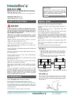
CONNECTIONS
ELECTRICAL & MECHANICAL FEATURES
Power Supply
Must use NEC Class 2 or Limited Power Source (LPS) and SELV
rated power supply.
If using DC power supply:
Respect polarity applied of terminals (+) and (-). Be sure the voltage applied is within the range admitted
(check table below). The power supply can be connected to earth but only through the negative terminal,
never through the positive terminal.
If using AC power supply:
Make sure the voltage applied is of the value admitted (24 Vac). Do not connect any of the terminals of the
AC power supply to earth, and make sure the same power supply is not supplying any other device.
Ethernet / BACnet IP (UDP) / Modbus TCP (TCP) / Console (UDP & TCP)
Connect the cable coming from the IP network to the connector ETH of the gateway. Use an Ethernet CAT5
cable. If communicating through the LAN of the building, contact the network administrator and make sure traffic
on the port used is allowed through all the LAN path (check the gateway user manual for more information).
Default IP is 192.168.100.246.
PortA / Modbus RTU
Connect the EIA485 bus to connectors A3 (+), A4 (-
) and A1 or A2 (SNGD) of gateway’s PortA. Respect the
polarity.
PortB / BACnet MSTP
Connect the EIA485 bus to connectors B1 (-), B2 (+) and B3 (SNGD) of
gateway’s PortB. Respect the polarity.
Note for PortA and PortB; Remember the characteristics of the standard EIA485 bus: maximum distance of
1200 meters, maximum 32 devices connected to the bus, and in each end of the bus it must be a termination
resistor of 120 Ω. The gateway has an internal bus biasing circuit that incorporates the termination resistor. If you
install the gateway in one of the ends of the bus, then do not install an additional termination resistor in that end.
Console Port
Connect a mini-type B USB cable from your computer to the gateway to allow communication between the
Configuration Software and the gateway. Remember that Ethernet connection is also allowed. Check the user
manual for more information.
USB
Connect a USB storage device (not a HDD) if required. Check the user manual for more information.
Power Supply
Ethernet
Modbus TCP
BACnet IP
USB
storage
BACnet MSTP
Console
Port
100 mm (h)
100 mm (w)
130 mm (d)
Modbus RTU
EIA485