background image

19

Version 1.0 (11/2007) en                   

Original language

RollerDrive EC200

Assembly

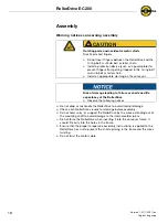
Warning notices concerning the electrical installation

¾

The electrical installation may only be executed by qualified and authorized 
persons.

¾

Disconnect the power before installing, removing or rewiring the RollerDrive.

¾

Do not apply AC current to the RollerDrive or DriveControl device at any time 
as this will cause irreparable damage.

¾

Do not apply too much stress to the connector pins. Bending the wires at the 
connector and forcing the star washer over them can cause damage to the 
insulation of the wires, which could result in failure of the RollerDrive.

¾

Ensure that the RollerDrive, the DriveControl and the 24 VDC power source 
are properly earthed through the frame or supporting structure in which the 
RollerDrive and the DriveControl are installed. Failure to do so could cause 
the buildup of static electricity or ground loops and can cause the motor or 
DriveControl to malfunction or fail prematurely.

¾

Do not bend the motor cable at the motor shaft. Leave a minimum of 12 mm 
(0.5 in) of excess cable for stress relief. (Minimum motor cable bend radius 5x 
cable diameter.)

¾

Do not spin the RollerDrive manually, as this generates an induction voltage 
which could damage the DriveControl.

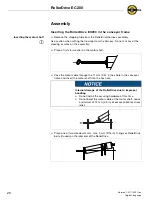
Setting up a roller conveyor

A roller conveyor usually consists of conveyor zones. Each zone is composed of 
one RollerDrive and several idler rollers which are driven by the RollerDrive. The 
idler rollers can be linked using either flat belts, timing belts, O-ring belts, multi-
rib belts or roller chains. The number of idler rollers in each zone depends on the 
application.

¾

Before installing the RollerDrive, define the position of the conveyor zone 
within the conveyor and the position of the RollerDrive within the conveyor 
zone.

Risk of damage to the motor and/or the wires of the 
RollerDrive

¾

Observe the following notices.

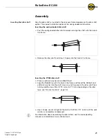
Hint

Locate the RollerDrive near the center of the zone or the center of gravity of the 
object being conveyed to improve the transmission of the force between 
RollerDrive and goods.

Содержание RollerDrive EC200

Страница 1: ...User Manual Interroll RollerDrive EC200...

Страница 2: ...l 1 910 799 11 00 Fax 1 910 392 38 22 www interroll com Copyright The copyright of this manual remains with Interroll Corporation This manual includes regulations and technical drawings which may not...

Страница 3: ...Dimensions of the motor shaft 13 Dimensions of idler cartridges 14 Groove locations 15 Conical RollerDrives 16 Transport and storage Transport 17 Storage 17 Assembly Warning notices concerning assembl...

Страница 4: ...oes not accept any liability for malfunctions or defects due to non observance of this manual If you have any questions after reading the user manual feel free to contact our customer service See the...

Страница 5: ...on Further symbols This symbol marks the steps that have to be carried out This symbol identifies possible material damage Information about how to avoid the damage Important This symbol displays safe...

Страница 6: ...ds such as parts cartons totes or boxes It must be integrated in a conveyor module or a conveying system Any other use is considered inappropriate Use of the RollerDrive EC200 is only allowed in the a...

Страница 7: ...Drive for visible damage In case of fumes unusual noise or blocked or damaged goods stop the RollerDrive at once and ensure that the RollerDrive cannot be started accidentally Contact qualified person...

Страница 8: ...n be used in dusty and or moist environments due to its protection class IP54 or IP66 The RollerDrive EC200 is powered by a brushless electronically commutated 24 VDC motor with an integrated 4 quadra...

Страница 9: ...for more than 10 seconds the motor will be switched off and the failure signal will be set The RollerDrive EC200 will try to start again after 60 seconds If the RollerDrive is running at chosen speed...

Страница 10: ...o load current 0 4 A Maximum continuous current 2 1 A Maximum peak current 5 5 A Mechanical performance 25 W System efficiency drive 49 Maximum ripple from power supply 3 Noise emission mounted 55 dB...

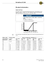
Страница 11: ...1 operation 6SHHG YV 7RUTXH XUUHQW YV 7RUTXH 7RUTXH LQ OE 7RUTXH 1P 7DQJHQWLDO IRUFH 7 OEI 7DQJHQWLDO IRUFH 7 1 V P G H H S 6 y y y y y y P S I G H H S 6 y y y y y y W Q H U U X V X y y y y 0D LPXP FR...

Страница 12: ...roll DriveControls DC EC200 EC300 13 1 or Z Card EC 6SHHG YV 7RUTXH XUUHQW YV 7RUTXH 7RUTXH LQ OE 7RUTXH 1P V P G H H S 6 y y y y y y P S I G H H S 6 y y y y y y W Q H U U X V X y y y y 0D LPXP FRQWLQ...

Страница 13: ...ailure output Low no failure High failure 5 gray Speed start signal analog Range 0 to 24 VDC Stop brake 0 to 2 VDC Speed 2 4 VDC to 5 VDC Incline ratio 1 V 114 6 revs min gear ratio Max speed 5 VDC to...

Страница 14: ...rive does not run within the specified tolerance of 5 Rotary switch speed setting at DriveControl Voltage setting on pin 5 VDC Speed of transport m s ft min 5 Gear ratio 12 1 Gear ratio 16 1 Gear rati...

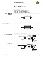
Страница 15: ...RLEU is mainly used in Europe and Asia RLUS is mainly used in North and South America Spring loaded 11 mm 0 44 in hex Female threaded M8 FTM8 floating Dimensions of the motor shaft Standard configurat...

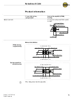
Страница 16: ...g Straight O ring hub Multi rib hub Timing belt hub Poly Chain GT 8 mm pitch 18 teeth RLEU RLUS 5 mm 0 2 in 15 5 mm 0 61 in 5 8 5 86 PP LQ PP LQ PP LQ PP LQ 5 8 5 86 PP LQ PP LQ m PP LQ PP LQ PP LQ 5...

Страница 17: ...shaft 3 8 in pitch 20 teeth 11 mm 0 44 in hex spring loaded Female threaded M8 FTM8 floating 9 5 mm 0 37 in 16 8 mm 0 66 in 35 mm 1 38 in RLEU RLUS 60 9 mm 2 4 in PLQ PP LQ PLQ PP LQ IRU WXEH GLDPHWH...

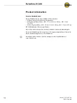
Страница 18: ...1 mm 0 44 in RLUS B F 3 mm 0 12 in With O ring hub RLEU B F 37 mm 1 46 in RLUS B F 3 mm 0 12 in B F Width between the conveyor frames Due to the conical sleeves they are only available in certain stan...

Страница 19: ...arranty report any damage caused by transport instantly to the transport company and Interroll Do not transfer the RollerDrives between warm and cold environments This may cause condensing water Stora...

Страница 20: ...e holes in the frame Ensure that the proper torque see assembly instructions is applied to the RollerDrive hex nut to prevent the shaft spinning in the frame and the wires twisting Do not twist the mo...

Страница 21: ...r DriveControl to malfunction or fail prematurely Do not bend the motor cable at the motor shaft Leave a minimum of 12 mm 0 5 in of excess cable for stress relief Minimum motor cable bend radius 5x ca...

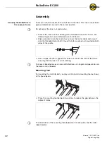
Страница 22: ...conveyor frame and insert the motor shaft into the hex hole Place one or two standard 4 mm max 5 mm 3 16 in O rings or RollerDrive belts if used on the idler end of the RollerDrive Hint Use caution w...

Страница 23: ...allow it to pop into the hole in the frame Inserting the FTM8 idler shaft Place a split lock washer onto a M8x20 bolt Align the RollerDrive with the hole in the frame and thread the M8 bolt and split...

Страница 24: ...threaded motor shaft Ensure that star washers are mounted on both sides of the profile Use a torque wrench to tighten this outer nut with 35 Nm 308 in lbf while ensuring that the inner nut is not rota...

Страница 25: ...installation If you use the recommended DriveControl see DriveControls for the RollerDrive EC200 page 10 connect the motor plug to the DriveControl If you do not use the DriveControl connect your con...

Страница 26: ...or the way goods are placed on the conveyor Ensure that the RollerDrive is not blocked Procedure in case of accident or malfunction Stop the conveyor at once and ensure that it cannot be started accid...

Страница 27: ...roken down it has to be replaced Install a new RollerDrive see Abandonment page 27 and see Inserting the RollerDrive EC200 in the conveyor frame page 20 Cleaning Increased surface friction reduces the...

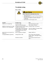
Страница 28: ...ply Plugs not connected properly Check cable connection RollerDrive is rotating in the wrong direction or at the wrong speed Wrong DriveControl setting at speed and direction rotary switch Change sett...

Страница 29: ...er shaft unscrew the bolt at the idler shaft Extract the RollerDrive from the conveyor frame Disposal The operator is responsible for the proper disposal of the RollerDrive In doing so industry specif...

Страница 30: ...lt Belts of 4 mm 0 16 in and max 5 mm 0 20 in diameter Multi rib belt Drive head with 9 grooves for flexible V ribbed belts PJ form ISO 9981 DIN 7867 Pitch 2 34 mm 0 09 in Belts with a max of 4 ribs P...

Страница 31: ...Machine Directive and therefore does not fully comply with the requirements of this directive It must not be put into service until the machinery into which it is to be incorporated has been declared...

Страница 32: ...WH ULYH 86 LOPLQJWRQ 1 7HO D XVD VDOHV LQWHUUROO FRP QWHUUROO DQDGD WG RUKDP 6WUHHW 1 1HZPDUNHW 2QWDULR DQDGD 7HO D FGQ VDOHV LQWHUUROO FRP QWHUUROO 6RXWK PHULFD DOOH 1R 158 6DQ 0DUWLQ 3URYLQFLD GH XH...

Отзывы: