International comfort products DFS2A/H 2X09 Скачать руководство пользователя страница 4

4

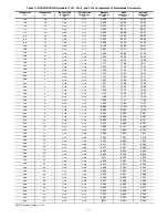
Table 2—Physical Data 

 Cooling Only

INDOOR UNIT

2 X DFF2AH09J1A

2 X DFF2AH12J1A

COOLING CAPACITY (Btuh) SEER

2 X 9,000

13.0

2 X 11,400

13.0

SYSTEM CHARGE (Ib)*

2 X 2.4

2 X 3.1

MOISTURE REMOVAL (pt/hr)

2 X 2.6

2 X 4.5

AIRFLOW (3 Speeds)

High / Med. / Low Cfm

2 X 350 / 2 X 280 / 2 X 220

2 X 350 / 2 X 280 / 2 X 220

DIMENSIONS LxHxW (in.)

32 3/32x10 15/64x7 9/32 32 3/32x10 15/64x7 9/32

REFRIGERANT TYPE

R

22

R

22

NET WEIGHT (Ib)

2 X 19.0

2 X 19.0

OUTDOOR UNIT

DFC2A318J2A

DFC2A324J2A

TUBE CONNECTIONS

Vert Lift/Vert Drop/Max Length (ft)

30/30/50

30/30/50

NOMINAL LINE SIZING

Mixed Phase...Suction (in.)

1/4...1/2

1/4...1/2

COMPRESSOR TYPE

Panasonic

2R13S126A6F

Panasonic

2P17SR126B1A

DIMENSIONS LxHxW(in.)

35.5 X 49.5 X 12.6

35.5 X 49.5 X 12.6

NET WEIGHT (Ib)

226

228

METERING TYPE

Piston (Accurator)

Piston (Accurator)

LEGEND

Accurator is non

serviceable

SEER

 — Seasonal Energy Efficiency Ratio

*Units are shipped with a factory charge based on 25 ft of refrigerant lines.

Table 3—Physical Data 

 Heat Pump

INDOOR UNIT

2 X DFF2AH09J1A

2 X DFF2AH12J1A

COOLING CAPACITY (Btuh)

SEER

2 X 9,000

13.0

2 X 11,400

13.0

HEATING CAPACITY (Btuh) 

HSPF

17,200

7.7

23,600

7.7

SYSTEM CHARGE (Ib)*

2 X 2.4

2 X 3.1

MOISTURE REMOVAL (pt/hr)

2 X 2.6

2 X 4.5

AIRFLOW (3 Speeds)

High / Med. / Low Cfm

2 X 350 / 2 X 280 / 2 X 220

2 X 350 / 2 X 280 / 2 X 220

DIMENSIONS LxHxW (in.)

32 3/32x10 15/64x7 9/32 32 3/32x10 15/64x7 9/32

REFRIGERANT TYPE

R

22

R

22

NET WEIGHT (Ib)

2 X 19.0

2 X 19.0

OUTDOOR UNIT

DFC2A318J2A

DFC2A324J2A

TUBE CONNECTIONS

Vert Lift/Vert Drop/Max Length (ft)

30/30/50

30/30/50

NOMINAL LINE SIZING

Mixed Phase...Suction (in.)

1/4...1/2

1/4...1/2

COMPRESSOR TYPE

Panasonic

2R13S126A6F

Panasonic

2P17SR126B1A

DIMENSIONS LxHxW(in.)

35.5 X 49.5 X 12.6

35.5 X 49.5 X 12.6

SHIPPING WEIGHT (Ib)

226

228

METERING TYPE

Piston (Accurator)

Piston (Accurator)

LEGEND

Accurator is non

serviceable

HPSF

 — 

Heating Seasonal Performance Factor

SEER

 — Seasonal Energy Efficiency Ratio

*Units are shipped with a factory charge based on 25 ft of refrigerant lines.
NOTE: Standard Ambient Operating Limitations 

 55  F to 125  F (12.7  C to 51.6  C).

Содержание DFS2A/H 2X09

Страница 1: ...and NOTE The signal words DANGER WARNING CAUTION and NOTE are used to identify levels of hazard serious ness The signal word DANGER is only used on product labels to signify an immediate hazard The signal words WARNING CAUTION and NOTE will be used on product labels and throughout this manu al and other manuals that may apply to the product DANGER Immediate hazards which will result in se vere per...

Страница 2: ...nd 2 for minimum required distances between unit and walls or ceilings S Indoor and outdoor units should be installed at a Mini mum length of 10 ft apart Maximum line length of 50 ft and vertical separation of 30 ft S Do not install indoor units near a direct source of heat such as direct sunlight steam or flame UNIT COMPONENT DAMAGE Failure to follow this caution may result in damage to unit comp...

Страница 3: ...Cushions Electric Terminals Remote Controller Mounting Bracket Remote Controller and Batteries Insulation for Indoor Fittings Owner s Manual Wall mounted Receiver RTX 2 X 1 2 X 8 2 X 1 2 X 1 2 X 1 2 X 1 2 X 1 Mounting Bracket with 2 screws 2 X 8 4 1 OPTIONAL Not Included DFF2A DFF2H 09 12 Available for HEAT PUMP ONLY NADA001TW ...

Страница 4: ... refrigerant lines Table 3 Physical Data Heat Pump INDOOR UNIT 2 X DFF2AH09J1A 2 X DFF2AH12J1A COOLING CAPACITY Btuh SEER 2 X 9 000 13 0 2 X 11 400 13 0 HEATING CAPACITY Btuh HSPF 17 200 7 7 23 600 7 7 SYSTEM CHARGE Ib 2 X 2 4 2 X 3 1 MOISTURE REMOVAL pt hr 2 X 2 6 2 X 4 5 AIRFLOW 3 Speeds High Med Low Cfm 2 X 350 2 X 280 2 X 220 2 X 350 2 X 280 2 X 220 DIMENSIONS LxHxW in 32 3 32x10 15 64x7 9 32 ...

Страница 5: ... D I S T F E L W E I V P O T A C B 20 06 2006 GAD L EITANC NEW 5 8 1 0 6 2 5 1 8 0 3 2 5 3 6 5 3 6 7 2 1 0 4 0 5 7 2 8 0 2 3 6 9 1 6 0 1 4 1 2 1 7 5 1 6 0 9 5 2 8 2 7 3 2 0 1 0 6 2 5 1 8 0 3 2 5 3 6 5 8 1 7 2 1 0 4 0 5 7 2 5 3 6 4 1 2 1 5 2 b l 7 8 1 6 9 1 6 0 1 7 5 1 6 0 9 8 2 7 3 2 0 1 8 0 2 3 A 1 J 9 0 H A 2 F F D A 1 J 9 0 H H 2 F F D A 1 J 2 1 H A 2 F F D A 1 J 2 1 H H 2 F F D P C I ...

Страница 6: ...TANC SUPERSEDES NEW REV W E I V P O T E G R A H C S I D R I A N I R I A VIEW S E C N A R A E L C M U M I N I M 1 E T O N E E S G N I T U O M T O L S N O I T C E N N O C R E W O P D L E I F N O I T C E N N O C L O R T N O C R E V O C S I H T R E D N U 3 E T O N E E S P Y T º 0 3 E N I L R O P A V A I D P N O I T C E N N O C E R A L F T R O P E C I V R E S N O I T C E N N O C E R A L F 5 2 T R O P E...

Страница 7: ...en the indoor and outdoor units drill a 2 5 in hole through the wall for the refrigerant lines drainage hose and control cable passage as shown in Fig 5 1 Mark the center of the hole to be drilled according to the re frigerant line routing used and dimensions shown in Fig 4 2 Make sure to drill outwards and downwards so that the opening in the outside wall is at least 1 2 lower than the opening on...

Страница 8: ...nect the outdoor sensor TH3 to its mating black terminal See Fig 9 FIRE HAZARD Failure to follow this warning could result in personal injury death and or property damage Make sure that all wires and screws are firmly fastened WARNING REASSEMBLE 1 Connect the display connector to the display panel printed circuit board 2 Put the control box cover and grille frame back on using the appropriate scre...

Страница 9: ...pper refrigerant tubing No other type of tubing may be used Use of other types of tubing will void the manufacturer s warranty Do not open service valves or remove protective caps from tubing ends until all the connections are made Bend tubing with special bending tools to avoid the formation of sharp bends Take care to avoid kinks or flattening of the tubing Keep the tubing free of dirt sand mois...

Страница 10: ... expelled then refrigerant charge must be checked and adjusted Follow the steps below 1 Open the service port cap on the suction line valve large valve of unit No 1 2 Connect the vacuum pump to the service port of unit No 1 via the pressure gage and evacuate to 500 microns to eliminate contamination and moisture 3 Disconnect the vacuum pump Unit should maintain 500 microns for 5 minutes 4 Remove t...

Страница 11: ...oth sections NOTE Specifications and performance data are subject to change with out notice 3095897 Table 5 Electrical Data Outdoor Units 115 1 60 UNIT VOLTAGE MCA MOCP FULL LOAD AMPS FAN MO TOR AMPS COM PRESSOR AMPS COMPRESSOR LOCKED ROTOR AMPS DFC2A 318J2A 115VAC 19 8 25 18 1 00 7 2 42 DFC2H 324J2A 115VAC 24 6 30 22 2 1 00 9 3 58 LEGEND MCA Minimum Circuit Amps MOCP Maximum Overcurrent Protectio...

Страница 12: ...6 J 7 J 8 J N A F S V R P M O C 8 1 J 6 K 5 K 1 K 2 K STEPPER R O T O M 8 K 9 K 7 K 1 1 J 4 1 J K L B D E R 1 3 V 2 1 V 2 1 K L B H W D E R N E E R G C D L B R O T O M 1 J 5 J 1 3 3 J 4 J 1 H T l o r t n o c 0 7 6 C A T n i a M 1 7 6 C A T d r a o B B 2 7 6 C A T l o r t n o C r o t o M M 1 2 3 L E Y L E Y R G 2 3 4 6 5 B T V T L H 1 R O R O D N G 3 H T K L B 1 2 3 4 5 6 BLK W H T BRN R ED BLK YEL...

Страница 13: ... 5 B T V T L H 1 R O D N G K L B T I N U R O O D N I 2 H T H W N E E R G D E R 2 1 J 6 J 7 J 8 J N A F S V R P M O C 8 1 J 6 K 5 K 1 K 2 K STEPPER R O T O M 8 K 9 K 7 K 1 1 J 4 1 J K L B D E R 1 3 V 2 1 V 2 1 K L B H W D E R N E E R G C D L B R O T O M 1 J 5 J 1 3 3 J 4 J 1 H T l o r t n o c 0 7 6 C A T n i a M 1 7 6 C A T d r a o B B 2 7 6 C A T l o r t n o C r o t o M M 1 2 3 L E Y L E Y R G 2 3...

Страница 14: ...nd install lockout tag 2 Using a garden hose or other suitable equipment flush coil from the outside to remove dirt Be sure to flush all dirt and debris from drain holes in base of unit Fan mo tors are waterproof Indoor Units ELECTRICAL SHOCK HAZARD Failure to follow this warning could result in personal injury or death To avoid the possibility of electric shock before performing any cleaning and ...

Страница 15: ...he start of each cooling season Check the flow by pouring water into the drain Clean or Replace Drain Pan The drain pan should only be cleaned or replaced by a qualified service technician 1 Place a plastic sheet on the floor to catch any water that may spill from the drain pan 2 Remove the intake grille and distribution assembly 3 Remove the condensate water in the drain pan by letting water drai...

Страница 16: ...ect resistance Check for proper connection Replace thermistor if necessary 3 Flashes Low Pressure Check system pressures Check refrigerant charges Check thermistors TH1 and TH2 for correct resistance 4 Flashes High Pressure Check system pressures Check refrigerant charges Check thermistors TH1 and TH2 for correct resistance 5 Flashes Low Voltage Check operating voltage Check electrical connections...

Страница 17: ...74 13 25 35 6 2 1 8 1 0 11 75 12 22 12 70 37 4 3 1 8 1 0 11 28 11 73 12 18 39 2 4 1 8 1 0 10 83 11 25 11 68 41 0 5 1 8 1 0 10 40 10 80 11 21 42 8 6 1 8 1 0 9 986 10 370 10 76 44 6 7 1 8 1 0 9 595 9 960 10 33 46 4 8 1 8 1 0 9 222 9 569 9 921 48 2 9 1 8 1 0 8 866 9 196 9 530 50 0 10 1 8 1 0 8 526 8 840 9 157 51 8 11 1 8 1 0 8 197 8 496 8 797 53 6 12 1 8 1 0 7 883 8 167 8 453 55 4 13 1 6 0 9 7 583 7 ...

Страница 18: ...7 2 2 1 2 2 264 2 352 2 441 118 4 48 2 3 1 3 2 192 2 227 2 364 120 2 49 2 3 1 3 2 122 2 206 2 291 122 0 50 2 3 1 3 2 055 2 137 2 220 123 8 51 2 3 1 3 1 990 2 070 2 151 125 6 52 2 3 1 3 1 928 2 006 2 085 127 4 53 2 3 1 3 1 867 1 943 2 021 129 2 54 2 3 1 3 1 809 1 883 1 959 131 0 55 2 5 1 4 1 753 1 826 1 900 132 8 56 2 5 1 4 1 699 1 770 1 842 134 6 57 2 5 1 4 1 647 1 717 1 787 136 4 58 2 5 1 4 1 597...

Страница 19: ... fan motor In Heat mode Delayed start for indoor fan motor Normal software delay maximum of 20 sec Clogged air filters Clean filters Low Capacity Lack of refrigerant Ice formation on the evapora tor coil Unit must be charged according to the nameplate after local izing the gas leak Clogged air filters Clean filters In Heat Mode Only Compressor Runs Out door and Indoor Fan Motors are Stopped A C op...

Отзывы: