


INSTALLATION INSTRUCTIONS
R-22 Split System Air Conditioner
421 01 5001 00
7
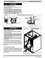
F. SERVICE VALVES
Service valves are closed and tube stubs are plugged
from the factory. Outdoor units are shipped with a
refrigerant charge sealed in the unit. Leave the service
valves closed until all other refrigerant system work is
complete or the charge will be lost. Leave the plugs in
place until line set tubing is ready to be inserted.
Service valve bodies are brass and tube stubs are
copper.
G. BRAZING CONNECTIONS
!
WARNING
FIRE HAZARD
Failure to remove refrigerant and oil charge before
brazing could result in personal injury, death, and/
or property damage.
Refrigerant and oil mixture could ignite and burn
as it escapes and contacts brazing torch. Make
sure the refrigerant charge is properly removed
from both the high and low sides of the system be‐
fore brazing any component or lines.
Clean line set tube ends with emery cloth or steel brush.
Remove any grit or debris.
Insert line set tube ends into service valve tube stubs.
Apply heat absorbing paste or heat sink product between
service valve and joint. Wrap service valves with a heat
sinking material such as a wet cloth.
Braze joints using a Sil-Fos or Phos-copper alloy.
!
CAUTION
PRODUCT DAMAGE HAZARD
Failure to follow this caution may result in product
damage.
Braze with Sil-Fos or Phos-copper alloy on cop‐
per-to-copper joints and wrap a wet cloth around
rear of fitting to prevent damage to TXV.
H. EVACUATING LINE SET AND INDOOR COIL
The unit is shipped with a factory refrigerant charge. The
liquid line and suction line service valves have been
closed after final testing at the factory. Do not disturb
these valves until the line set and indoor coil have been
evacuated and leak checked, or the charge in the unit
may be lost.
NOTE:
Do not use any portion of the factory charge for
purging or leak testing. The factory charge is for filling the
system only after a complete evacuation and leak check
has been performed.
!
CAUTION
PRODUCT DAMAGE HAZARD
Failure to follow this caution may result in product
damage.
Never use the outdoor unit compressor as a vacu‐
um pump. Doing so may damage the compressor.
Line set and indoor coil should be evacuated using the
recommended deep vacuum method of 500 microns. If
deep vacuum equipment is not available, the alternate
triple evacuation method may be used by following the
specified procedure.
If vacuum must be interrupted during the evacuation
procedure, always break vacuum with dry nitrogen.
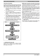
Deep Vacuum Method
The deep vacuum method requires a vacuum pump
capable of pulling a vacuum to 500 microns and a vacuum
gauge capable of accurately measuring this vacuum
level. The deep vacuum method is the most positive way
of assuring a system is free of air and water.
Watch the vacuum gauge as the system is pulling down.
The response of the gauge is an indicator of the condition
of the system (refer to Figure 6).
With no leaks in the system, allow the vacuum pump to
run for 30 minutes minimum at the deep vacuum level.
Figure 6
Deep Vacuum Gauge Response
and System Conditions
500
MINUTES
0
1
2
4
6
1000
1500
LEAK IN
SYSTEM
VACUUM TIGHT
TOO WET
TIGHT
DRY SYSTEM
2000
M
ICRONS
2500
3000
3500
4000
4500
5000
3
7
5