background image

Uninterruptible Power Supply Instructions

9

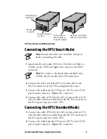
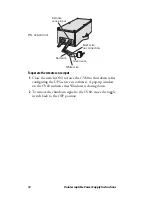
UPS Front View and UPS Back View 

Connecting the UPS (Smart Mode)

1

Attach the RS–232 cable (P/N 321-593-002) to COM1 or 
COM2 on the CV60 and tighten the screws to the DB–9 
connector.

2

Connect the other end of the RS–232 serial cable to the 
RS-232 connector on the UPS and tighten the screws.

3

Connect the cable from the UPS power OUT to the CV60 
power input connector. Tighten the connector. 

4

Connect the cable (P/N 226-341-005, six foot cable or P/N 
226-341-006, three foot cable) from the DC-DC converter to 
the DC input connector on the UPS. 

Connecting the UPS (Standard Mode)

1

Connect the cable (P/N 226-341-005, six foot cable or P/N 
226-341-006, three foot cable) from the DC-DC converter to 
the DC input connector on the UPS. 

2

Connect the cable from the UPS power OUT to the CV60 
power input connector. Tighten the connector. 

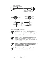
Note: 

Remove the dust cover from the serial port 

before connecting the cable.

Note:

 If you have a PicoLink radio installed, only 

COM1 may be used for the UPS connection.

OUT

Power/Charge
status LED

RS-232
connector

Power connector
to CV60

DC input from
vehicle battery
or power supply

Remote sense input
(Optical connection)

Содержание 851-059-003

Страница 1: ...Uninterruptible Power Supply UPS Instructions...

Страница 2: ...ct to change without prior notice and do not represent a commitment on the part of Intermec Technologies Corporation 2006 2009 by Intermec Technologies Corporation All rights reserved The word Interme...

Страница 3: ...Record This page records changes to this document The document was originally released as Revision 001 Version Number Date Description of Change 003 03 2009 Corrected information in the installation...

Страница 4: ...iv Uninterruptible Power Supply Instructions...

Страница 5: ...ode 9 Understanding the Power Charge Status LED 10 Using the Remote Sense Input Optional CV60 Only 10 Configuring the UPS Service 13 Windows XP 13 Windows CE 13 Typical UPS Installation Configurations...

Страница 6: ...vi Uninterruptible Power Supply Instructions...

Страница 7: ...tery charges Allow four hours for a complete charge When external power is removed from the UPS the battery immediately reverts from a charge mode to a discharge mode The output load maintains without...

Страница 8: ...condition there will be no means to determine when the UPS battery is almost at the point of no power The 5055 and a CV60 that is configured to work with Standard Mode immediately powers down at point...

Страница 9: ...26 341 006 three foot cable from the DC DC converter to the DC input connector on the UPS Connecting the UPS Standard Mode 1 Connect the cable P N 226 341 005 six foot cable or P N 226 341 006 three f...

Страница 10: ...CV60 via the Primary Power Fail and Low Battery lines These two signals immediately cause the CV60 to begin the shut down process The UPS should be configured in the Smart Mode for this operation A s...

Страница 11: ...We recommend an SPST switch single pole single throw rated at 24 VDC at 1 mA or less for the remote sense option Note Use a sealed switch for high humidity and dusty environments Follow customary ele...

Страница 12: ...CV60 to shut down after configuring the UPS service in software A pop up window on the CV60 indicates that Windows is closing down 2 To remove the shutdown signal to the CV60 move the toggle switch ba...

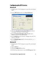
Страница 13: ...the UPS service to start at login 4 In the Critical Level Shutdown Time out field select Manual or 10 20 30 second intervals 5 In the COM Port field select the COM port where the UPS device is connect...

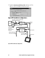
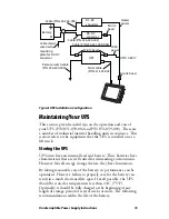
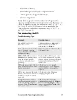
Страница 14: ...s Typical UPS Installation Configuration Battery Ferrite NF 130 P N 309 065 006 loop through one time Ferrite bead Dual output converter Ferrite bead Heater power CV60 Power Ferrite Bead Cable P N 226...

Страница 15: ...they have limitations By taking reasonable care of the battery its performance can be optimized However failure to properly care for the battery can result in a much shortened life span If at all poss...

Страница 16: ...the UPS is available to supply power but there is no load connected to it this state causes the battery to become discharged within several days Charging Shutting Down the UPS An optional charger shut...

Страница 17: ...the UPS 2 Remove the six screws from the battery access cover 3 Remove the cover Grasp the pull tabs firmly and pull to remove battery 4 Lift up the battery and remove the battery cable end clip To i...

Страница 18: ...ly installed UPS unit to charge on the lift truck for four hours prior to using This allows the battery to charge adequately When the main power to the UPS is removed the internal battery allows the c...

Страница 19: ...own the CV60 with a low battery Defective serial cable between the UPS and CV60 UPS and DC DC Converter LEDs are both flashing about once per second and the computer terminal doesn t power up Fault co...

Страница 20: ...th Avenue West Everett Washington 98203 U S A tel 425 348 2600 fax 425 355 9551 www intermec com 2009 Intermec Technologies Corporation All rights reserved Uninterruptible Power Supply UPS Instruction...

Отзывы: