2
truVision DVR 31 Quick Start Guide
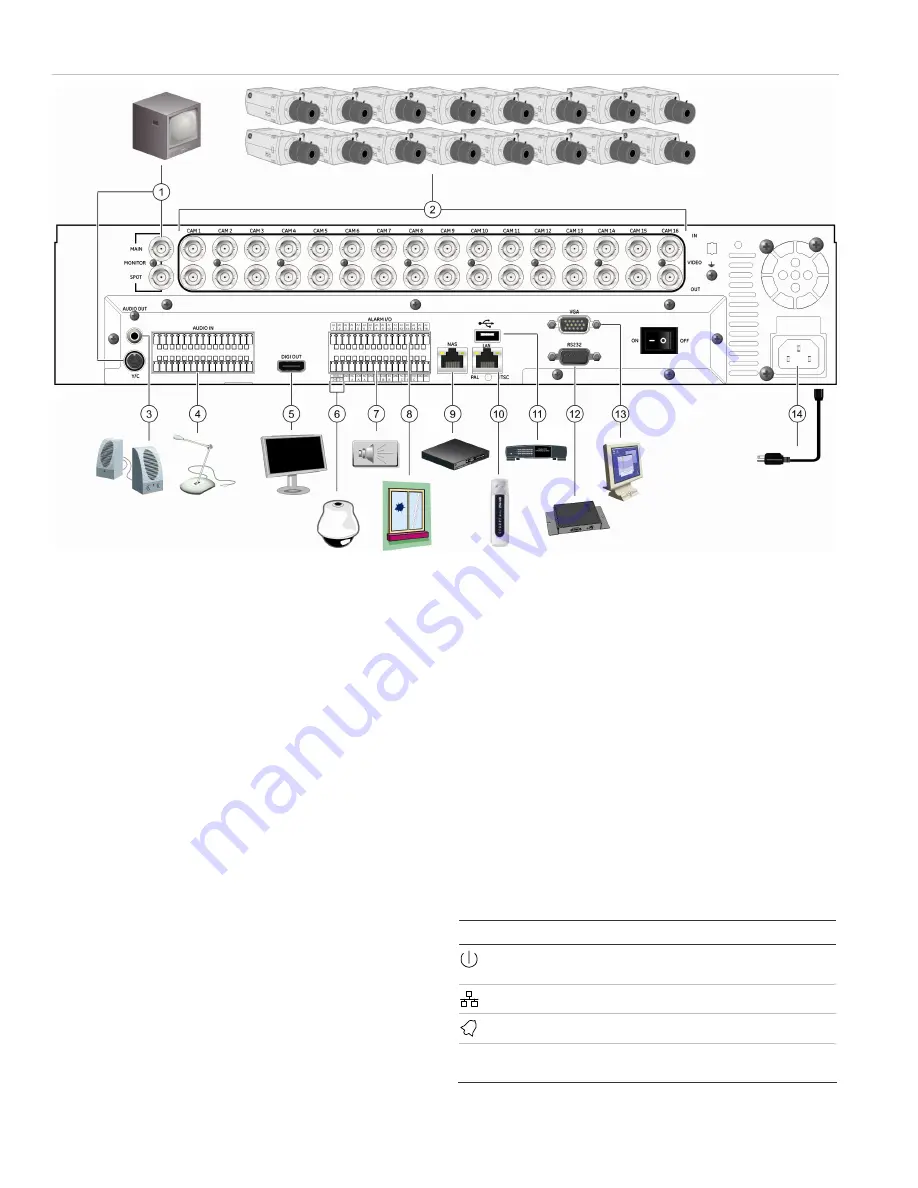
Figure 1: DVR 31 back panel connection diagram
1.
Connect up to two CCTV monitors (main and spot)
2.
Connect up to 16 cameras
3.
Connect to speakers for audio output
4.
Connect to audio input (available for each camera)
5.
Connect to a monitor that displays digital video (HDMI)
6.
Connect to a PTZ control
7. Alarm
output
8.
Connect to alarm input cables
9.
Connect to a network attached storage (NAS) device (This device
is currently not supported.)
10. Connect to a network
11. Connect to a USB device
12. Connect to a point-of-sale (POS) device
13. Connect to a VGA monitor
14. Connect to the power cord
Note:
During setup you can disable the password to
save time (Menus > Users > Enable Password). Be sure
to enable the password (if the installation requires it)
after completing the setup.
Connecting the devices
Use Figure 1 above as a visual guide to connect the
various peripherals to the DVR 31.
Resolution options: 800 x 600, 1024 x 768, 1280 x 1024,
720P, and 1080P*.
* See Appendix A in the truVision DVR 31 User Manual
for a list of compatible HDMI monitors.
Turning on the DVR 31
Turn on the DVR 31 using the power switch on the back
panel. When you turn on the device, the DVR 31
automatically displays all live views from the connected
cameras. It also automatically begins recording.
Operating the DVR 31
Status LEDs
The LEDs on the front panel light up or flash to alert you
to various conditions.
Table 1: Status LED descriptions
LED Name
Description
Power
Steady indicates that the correct power is
connected to the unit.
Network
Blinking indicates that data is being transferred.
Alarm
Steady indicates that an alarm is triggered.
REC Record
Blinking indicates that the DVR 31 is recording.
Steady indicates hard drive failure.


