


© 2019 United Technologies Corporation.
P/N 1072772-EN • REV C • ISS 01FEB19
Interlogix is part of UTC Climate, Controls & Security, a unit of United Technologies Corporation. All rights reserved. All trademarks are the
property of their respective owners. Information in this document is subject to change without notice.
NS3550-8T-2S Quick Installation Guide
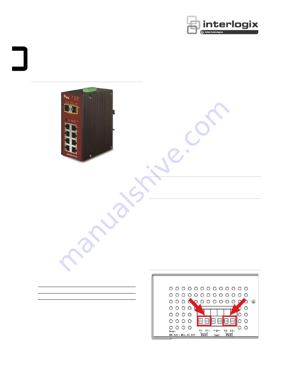
Figure 1: NS3550-8T-2S Industrial L2+ Multi-Port Managed
Ethernet Switch
Package contents
Thank you for purchasing the NS3550-8T-2S IFS L2+ industrial
managed switch. The description of this model is as follows:
Industrial L2+ 8-Port 10/100/1000T
+ 2-Port 100/1000X SFP Managed Switch
Unless specified, the term “industrial managed switch”
mentioned in this quick installation guide refers to the NS3550-
8T-2S.
Open the box of the industrial managed switch and carefully
unpack it. The box should contain the following items:
The industrial managed switch × 1
Quick installation guide × 1
CD with user manual × 1
DIN rail kit × 1
Wall mounting kit × 1
Dust cap (see the table below)
RJ45 Dust Cap
SFP Dust Cap
NS3550-8T-2S
8
2
If any of these are missing or damaged, contact your dealer
immediately. If possible, retain the carton including the original
packing materials for repacking the product in case there is a
need to return it to us for repair.
Requirements
The industrial managed switch provide
s a
remote login
interface for management purposes. The following equipment
is necessary for further management:
Workstations running Windows
®
XP / 2003 / Vista / 7 / 8 /
2008 / 10, MAC OS X or later, Linux, UNIX, or other
platforms are compatible with TCP/IP protocols.
Workstations are installed with Ethernet NIC (Network
Interface Card).
Serial port connection (Terminal)
The above workstations come with a COM Port (DB9)
or USB-to-RS-232 converter.
Ethernet port connection
Network cables – Use standard network (UTP) cables
with RJ45 connectors.
The above workstations have a web browser and
JAVA runtime environment plug-in installed.
Note
: We recommend using Internet Explorer 8.0 or later to
access the industrial managed switch. If the web interface of
the managed switch is not accessible, turn off the anti-virus
software or firewall and then try it again.
Wiring the power inputs
The upper panel of the industrial managed switch indicates a
DC inlet power socket and consists of one terminal block
connector within six contacts. Follow the steps below to insert
the power wire:
1. Insert the positive/negative DC power wires into contacts 1
and 2 for Power 1, or 5, and 6 for Power 2.
NS3550-8T-2S: DC 12 to 48 V
Figure 2: Managed industrial switch upper panel


