


Page 9
FUNCTION DEFINITIONS (CONT)
Full Scale Number (FS) {00001 to +99999}
(FS) is for scaling the analog outputs of the indicator. Both the +10V output and the 4-20 mA
outputs are automatically scaled by (FS). (FS) = the display value that corresponds to the full
scale spans of the outputs, either 10V or 16 mA. Changing the (FS) has no effect until a
calibration is performed. The scaling is accomplished along with the calibration procedure. The
TARE function operates on the analog output the same as it does on the digital display. The
analog output is a continuously amplified analog signal even though the gain is digitally
controlled. Therefore the polarity of the analog output is always the same as the signal input.
The 4-20 mA output is unipolar and therefore must always be used with a positive input signal.
Examples:
1. A 9834 is to read 10000 on the display and produce 5.000 V output with a
10,000 lbf load cell loaded to capacity. (FS) = 10000*10V/5V = 20000.
2. A 9834 is to read 2000.0 on the display and produce a 10 mA span output with a
2000 lbf load cell loaded to capacity. (FS) = 2000.0*16mA/10mA = 3200.0. The
output will then be 4 mA at zero load and 14 mA at capacity.
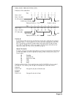
Setpoint 1 to Monitor (SP1 -) {SP1 , SP1 , SP1 , SP1 }
This function allows Setpoint 1 to monitor the instantaneous, peak, valley or peak minus valley
displays. The Increment or Decrement switches are used to cycle through the various displays.
To signify which display is being monitored, the least significant 7-segment display will be
illuminated as shown below.
INSTANT
PEAK
VALLEY
PEAK-VALLEY
Setpoint 1 to be (SP1 HI) {SP1 HI, SP1 LO}
This allows Setpoint 1 to be a High or Low Setpoint. The Increment or Decrement switches are
used to cycle through the HI or LO selection.
A High Setpoint is disabled when the compared value is less than the Setpoint value. The High
Setpoint is enabled when the compared value is equal to or greater than the Setpoint value.
A Low Setpoint is disabled when the compared value is greater than the Setpoint value. The
Low Setpoint turns on when the compared value is equal to or less than the Setpoint value.
Set Setpoint 1 Value (SEt SP) {00000 to +99,999}
Setpoint 1 can be set for any value from 00000 to +99,999. This value along with the previous
selection of SP HI or SP LO determines when the optically isolated open-collector output
transisitors are activated and the SP1 annunciator illuminated.
For Setpoints 2, 3 and 4, refer to Setpoint 1 setup, shown above.
Hysteresis Low (HL) {000 to 200}
HL is the hysteresis value for all Setpoints set to SP LO. HL determines the value the displayed
reading must exceed the Setpoint value by before deactivating their respective opto isolated
open-collector output(s).
Hysteresis High (HH) {000 to 200}
HH is the hysteresis value for all Setpoints set to SP HI. HH determines the value the displayed
reading must get below the Setpoint value by before deactivating their respective opto isolated
open-collector output(s).


