


PROFESSIONAL POWER AMPLIFIER
1
V2-5000
Contents
Contents
Unpacking
.......................................................................................................................................2
Short Form Instructions
.................................................................................................................2
Installation
Environment....................................................................................................................................3
Important Safety Instructions.............................................................................................................3
Description
.......................................................................................................................................4
Features
............................................................................................................................................4
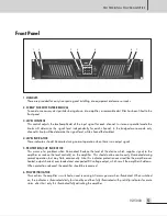
Front Panel
......................................................................................................................................5
Rear Panel
.......................................................................................................................................7
Applications
Stereo Installation ............................................................................................................................9
Parallel Installation ..........................................................................................................................9
Bridge Mono Installation ................................................................................................................10
Linked Installation..........................................................................................................................10
Connections ..................................................................................................................................11
Stereo/Parallel Connection ............................................................................................................12
Bridge Mono Connection ...............................................................................................................12
Block Diagram
..............................................................................................................................13
Specifications
................................................................................................................................14
Service
Procedures....................................................................................................................................16
Schematic .....................................................................................................................................16
Parts List .......................................................................................................................................16
Variations and Options
...............................................................................................................16
Warranty
.......................................................................................................................................16
Содержание V2-5000
Страница 1: ...Operation Manual Professional Power Amplifier V2 5000...
Страница 15: ...Block Diagram Block Diagrams PROFESSIONAL POWER AMPLIFIER 13 V2 5000...
Страница 17: ...PROFESSIONAL POWER AMPLIFIER 15 V2 5000 DIMENSIONS 440 482 88 369 39...
Страница 19: ......


