


Indoor Dry Bulb Temperature(F)
Heating Charge Chart
Outdoor Ambient Temperature(F)
Cooling Charge Chart
20
55
60
65
70
75
80
85
90
95
100
105
110
115
5
2
5
6
9
4
6
6
4
2
4
4
8
1
4
2
9
3
5
6
3
7
4
3
8
2
3
0
1
3
1
9
2
5
6
1
2
2
5
3
9
4
4
6
4
0
4
4
5
1
4
9
8
3
3
6
3
4
4
3
4
2
3
8
9
2
2
8
2
1
6
1
0
2
5
1
9
4
2
6
4
7
3
4
2
1
4
7
8
3
2
6
3
2
4
3
1
2
3
3
0
3
4
8
2
7
5
1
153
262
281
299
318
339
360
385
410
435
460
489
517
149
260
279
297
316
337
358
382
407
433
458
486
513
145
258
277
296
315
335
355
380
405
430
456
483
509
141
237
255
273
292
311
332
353
378
402
428
453
477
501
137
235
253
272
290
309
330
351
373
394
419
444
469
494
133
233
251
270
288
307
327
346
366
386
412
437
462
486
129
230
248
266
284
302
322
341
361
381
406
430
454
478
125
226
244
262
280
297
315
334
355
377
400
423
447
471
121
222
239
256
273
291
308
326
349
372
394
416
440
464
117
215
232
249
266
284
300
315
341
367
388
409
433
457
113
209
226
243
260
278
292
306
334
362
382
402
426
450
109
203
220
237
254
272
285
298
328
357
376
395
419
443
105
197
214
231
248
266
278
293
321
347
370
388
412
436
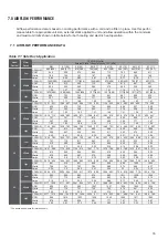
48K
Cooling Mode
60
62
64
66
68
70
72
74
76
78
80
82
135 333
340
347
354
361
370
382
390
398
406
414
426
128 325
332
339
346
353
360
376
383
390
397
404
416
121 318
325
332
339
346
353
367
374
381
388
396
408
114 310
317
324
331
338
347
358
366
374
382
390
402
107 302
309
316
323
330
337
348
355
362
369
379
391
100 295
302
309
316
323
330
338
345
352
359
369
379
93 287
294
301
308
315
322
330
337
344
351
359
368
86 278
285
292
299
306
313
319
327
335
343
351
359
79 269
276
283
290
297
304
310
318
326
334
342
350
72 258
265
272
279
287
295
305
312
319
326
333
342
4
3
3
6
2
3
9
1
3
0
1
3
4
0
3
3
9
2
5
6
8
2
3
1
2
3
3
1
3
5
0
3
9
9
2
8
5
51
301
308
316
323
44
304
311
317
37
307
314
30
48K
Heating Mode
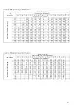
Table 7-8 Refrigerant charge for H/P system
Table 7-7 Refrigerant charge for H/P system
High Pressure Detected Valve(psig)
High Pressure Detected Valve(psig)
Low
P
re
ssure
De
tect
ed
V
alve(p
sig
)
Low
P
ressure
De
tec
ted
V
al
ve(psig
)


