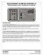
ELECTRONIC CLIMATE CONTROL II
SERVICE MANUAL Part No’s. 00-00855-000 / 00-00856-000
Intellitec
1485 Jacobs Rd.
Deland, FL 32724
386.738.7307
www.Intellitec.com
- 7 -
P/N 53-00855-856 Rev. C 080819
SYSTEM INTERCONNECTS:
12 VDC power is supplied to the control module via connector J1. This connector also provides the signal connections
between the control module and thermostat and the current sensor. Connector PC1B is part of the current sensor
assembly.
The pigtail connector, PC1A, is supplied with the system and is wired per the following table:
J1 PIN PC1B PIN
FUNCTION
COLOR
1
1
CURRENT SENSOR IN
WHT
2
2
CURRENT SENSOR GND
WHT
J1 PIN PC1A PIN
FUNCTION
COLOR
3
1
KEYED – NOT CONNECTED
4
2
+12 VDC POWER
RED
5
3
KEYED – NOT CONNECTED
6 4
POWER
GROUND
BLK
7 5
IPX
GND
BRN
8 6
IPX
SIG
YEL
THE ECC CURRENT SENSOR:
The current sensor is a transformer which converts the AC current passing through
its core into a corresponding voltage. A functional current sensor has a resistance
of approximately 15 - 40 Ohms and produces an AC voltage of 0.1 VAC per Amp of
current passing through the core (10 Amps = 1.0 VAC). The current sensor should
be mounted in one of the knockouts in the 120 VAC box so that the donut shaped
head is inside the box. The black wire feeding the 30 Amp main breaker in the 120
VAC panel should pass through the hole in the current sensor.
USE WITH 5 KW GENERATOR
In systems using 5 KW generator sets, an additional change-over, or transfer relay, is used to transfer the load of one of
the A/C system (usually the A/C1 system) to the generator’s second output to utilize generator’s full output capability. In
this situation, the ECC load shedding features will remain unchanged, but the current sensor will not measure the load
current going to the larger, A/C1 system when the generator is running. If the measured load currents through the current
sensor continue to exceed 30 Amps with the A/C2 system shed, the ECC Control Module will shed the A/C1 system to
prevent overload of the generator.
Current
Sensor


