


8
effective network connection
【
Installation
】
Before installation, confirm that the work environment meet the installation require, including the power needs and abundant space. Whether it is
close to the connection equipment and other equipments are prepared or not.
1. Avoid in the sunshine, keep away from the heat fountainhead or the area where in intense EMI.
2. Examine the cables and plugs that installation requirements.
3. Examine whether the cables be seemly or not (less than 100m) according to reasonable scheme.
4. Screw, nut, tool provide by yourself.
5. Power: redundant 12-48VDC power input
6. Environment: working temperature -40
~
85
℃
Relative humidity 5%
~
95%
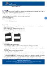
DIN rail installation
In order to use in industrial environments expediently, IES618-4D
series adopt 35mm DIN-Rail installation, the installation steps as fellows:
1. Examine the DIN-Rail attachment
2. Examine DIN Rail whether be firm and the position be suitability or not.
3. Insert the top of the DIN-Rail into the slot just below the stiff metal spring.
4. The DIN-Rail attachment unit will snap into place as shown below.
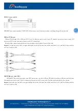
Wiring Requirements
Cable laying need to meet the following requirements,
1. It is needed to check whether the type, quantity and specification of cable match the requirement before cable laying;
2. It is needed to check the cable is damaged or not, factory records and quality assurance booklet before cable laying;
3. The required cable specification, quantity, direction and laying position need to match construction requirements, and cab le length depends
on actual position;
4. All the cable cannot have break-down and terminal in the middle;
5. Cables should be straight in the hallways and turning;
6. Cable should be straight in the groove, and cannot beyond the groove in case of holding back the inlet and outlet holes. C ables should be
banded and fixed when they are out of the groove;
7. User cable should be separated from the power lines. Cables, power lines and grounding lines cannot be overlapped and mixed whe n they
are in the same groove road. When cable is too long, it cannot hold down other cable, but structure in the middle of alignment rack;
8. Pigtail cannot be tied and swerved as less as possible. Swerving radius cannot be too small (small swerving causes terrible loss of link). Its
banding should be moderate, not too tight, and should be separated from other cables;


