background image


5


LED Indicator


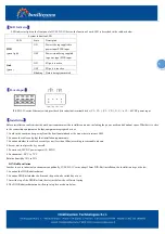
LED indicator light on the front panel of IT-ES215-IU Series .the function of each LED is described in the table as below. 

System indication LED 

LED 

State 

Description 

PWR 

(green light)


ON 

Power is being supplied to 

power input PWR input 

OFF 

Power is 

not

 being supplied 

to power input PWR input 

Link 

(green) 

ON 

FX port is active 

OFF 

FX port is inactive 

Blinking 

Data is being transmitted 


Power Input


          IT-ES215-IU series Ethernet switch provides 4 bits industrial terminal blocks (V1-, V1+), (V2-, V2+), V-, V+ is 12

48VDC power input.   


Installation


Before installation, confirm that the work environment meet the installation require, including the power needs and abundant space. Whether it is close 

to the connection equipment and other equipment are prepared or not.   

1. Avoid in the sunshine, keep away from the heat fountainhead or the area where in intense EMI.  

2. Examine the cables and plugs that installation requirements. 

3. Examine whether the cables be seemly or not (less than 100m) according to reasonable scheme.   

4. Screw, nut, tool provide by yourself. 

5. Power need: 24VDC power inputs (12~48DC


6. Environment: -40°C to 75°C 

Relative humidity 10% to 95% 

DIN Rail Installation 

In order to use in industrial environments expediently, IT-ES215-IU series adopt 35mm DIN-Rail installation, the installation steps as below, 

1. Examine the DIN-Rail attachment 

2. Examine DIN Rail whether be firm and the position be suitability or not. 

3. Insert the top of the DIN-Rail into the slot just below the stiff metal spring. 

4. The DIN-Rail attachment unit will snap into place as shown below. 


Содержание IT-ES215-IU Series

Страница 1: ...n fiber port is 100Base FX multi mode M single mode S SC ST optional Packing List The IT ES215 IU series switch is shipped with following items IT ES215 IU Ethernet switch Plus Terminal Block 1 Hardwa...

Страница 2: ...ernet port indicator 3 10Base T 100Base TX port 5 Power input terminal block 3 bits 6 Ground screw 7 DIN Rail mount IT ES215 IU 1F 1 Ethernet port indicator 2 Power indicator 3 100Base FX fiber port 4...

Страница 3: ...Dimensions Unit mm Communication Connector IT ES215 IU series industrial Ethernet switch provides 3 5 10 100BaseT X Ethernet ports RJ45 and 0 2 100Base FX fiber ports SC ST optional 10 100BaseT X Ethe...

Страница 4: ...ble MDI X Cross over cable 100BaseFX port 100Base FX full duplex SM or MM port SC ST type The fiber port must be used in pair TX transmit port connect remote switch s RX receive port RX receive port c...

Страница 5: ...it is close to the connection equipment and other equipment are prepared or not 1 Avoid in the sunshine keep away from the heat fountainhead or the area where in intense EMI 2 Examine the cables and...

Страница 6: ...nes and grounding lines cannot be overlapped and mixed when they are in the same groove road When cable is too long it cannot hold down other cable but structure in the middle of alignment rack 8 Pigt...

Страница 7: ...or DIN Rail Mounting Dimensions L H D 136 mm 105mm 52mm Working environment Operating Temperature 40 75 Storage Temperature 40 85 Relative Humidity 5 95 non condensing Approvals EMI FCC Part 15 CISPR...

Отзывы: