Intellinet 560535 Скачать руководство пользователя страница 48

48   


802.1x Setting 

The 802.1x Protocol provides port authentication and must be enabled globally for the switch system before port 

settings are active. 


Web Smart switch interface 

To configure 802.1x global settings: 

1. 

Click Security, 802.1x, 802.1x Setting. 

2. 

Set 802.1x to Enabled. 

3. 

Specify the RADIUS server IP address. 

4. 

Specify the RADIUS server shared key. 

5. 

Modified other parameters as required. 

6. 

Click Apply.   

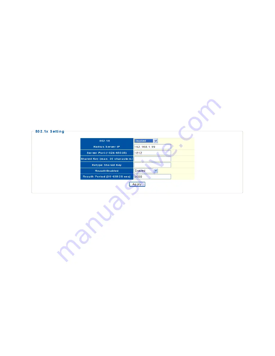
Figure 36:    802.1x Setting


Hint§ 

The following parameters are shown on the 802.1x screen: 

802.1x 

- Sets the global setting for 802.1x. (Default: Disabled) 

RADIUS Server IP 

- Address of the authentication server.


Server Port 

- Network (UDP) port of RADIUS server used for authentication messages. (Range: 1024-65535; 

Default: 1812)


Shared Key 

- Encryption key used for RADIUS server messages. Do not use blank spaces in the string. 

(Maximum length: 30 characters) 

Retype Shared Key 

- Re-type the string entered in the previous field to ensure no errors were made. The switch 

will not change the encryption key if these two fields do not match.


ReauthEnabled 

- Set clients to be re-authenticated after the interval specified by the Reauth Period. 

Re-authentication can be used to detect if a new device is plugged into a switch port. (Default: Enabled)


Reauth Period 

- Set the time period after which a connected client must be re-authenticated. (Range: 30-65535 

seconds; Default: 3600 seconds)


Содержание 560535

Страница 1: ...1 POE WEB MANAGED GIGABIT ETHERNET SWITCH with 2 SFP Ports USER MANUAL MODELS 560535 560559 INT 560535 560559 UM 0212 03 ...

Страница 2: ...k Group Setting 12 Trunk Distribution Algorithm Setting 13 LACP Setting 15 Static VLAN Table Setting 16 VLAN Port Setting 17 VLAN Stacking Table Setting 18 VLAN Stacking Setting 19 IGMP Multicast Group Information 21 IGMP Snooping 22 IGMP Global Setting 23 IGMP VLAN Setting 24 Spanning Tree 25 Spanning Tree Port Setting 27 Quality of Service QoS 29 Port based Priority Setting 29 DSCP based Priorit...

Страница 3: ...ng 40 Jumbo Frame Setting 42 Management Access Filter 43 CHAPTER 4 Security 45 MAC Address Information 45 Static MAC Setting 46 MAC Filtering Setting 47 802 1x Setting 48 802 1x Port Setting 49 IP Filter Configurations 50 Storm Control settings 52 Port Isolation 53 Defence Engine 54 CHAPTER 5 Monitoring 55 Port Statistics Information 55 CHAPTER 6 Tools 56 Http Upgrade 56 Reset Factory Defaults 57 ...

Страница 4: ...vices LEDs for power link activity and PoE Supports IEEE 802 3at af detection and short circuit overload and high voltage protection All RJ45 ports with Auto MDIX and NWay auto negotiation support Web based configuration Supports bandwidth control per port Supports SNMP management Supports VLAN tag based and port based Provides IEEE 802 1x port based security Supports link aggregation trunking Sup...

Страница 5: ...witch intuitively by interacting with the built in Web server The home page is displayed as shown below It displays the Main Menu on the left side of the screen and an image of the front panel on the right side The Main Menu is used to navigate to other menus and to display configuration parameters and statistics Figure 1 Home Page ...

Страница 6: ...ask is 255 255 255 0 Step 3 Open the browser such as Microsoft Internet Explorer and go to http 192 168 1 1 which is the switch address If your PC is properly configured you will see the login page below Figure 2 Login Popping Up Window NOTE If you do not see the login page check that Steps 1 and 2 were done correctly Step 4 Key in both the default user name admin and the password admin to pass th...

Страница 7: ...7 Figure 3 Web Based Management Interface ...

Страница 8: ...Information Web Smart switch interface Figure 4 System Information IP Address Setting To set up a static IP address for the switch Web Smart switch interface 1 Click System then IP Setting 2 Set the Mode to Static IP 3 Specify the IP address subnet mask and gateway address 4 Click Apply Figure 5 IP Setting ...

Страница 9: ...ctionality on the interface IPv6 Address Manually sets up a global unicast address by specifying the full address and network prefix length in the Prefix field Default null Prefix Length Defines the prefix length as a decimal value indicating how many contiguous bits starting at the left of the address comprise the prefix that is the network portion of the address Default 0 Router Sets up the IPv6...

Страница 10: ...word again to confirm your input 5 Click Save Figure 7 User Account Setting Port Setting To specify options for enabling auto negotiation or manually setting the speed and duplex mode or for enabling flow control To set up port configuration in the Web browser 1 Click System Port Setting 2 Select one or more ports to configure 3 Make any required changes to the connection settings 4 Click Apply ...

Страница 11: ...ion Default Auto negotiation enabled Auto Enables auto negotiation When using auto negotiation the optimal settings will be negotiated between the link partners based on their advertised capabilities Auto must be enabled for all 1 Gbps connections 100M Full Supports 100 Mbps full duplex operation 100M Half Supports 100 Mbps half duplex operation 10M Full Supports 10 Mbps full duplex operation 10M ...

Страница 12: ...p Web Smart switch interface 1 Click Configuration Link Aggregation Trunk Group Setting 2 Select the trunk group ID to be created or modified 3 Select the trunk type Static or LACP 4 Assign up to four port members to the trunk 5 Click Add Modify Figure 9 Trunk Group Setting ...

Страница 13: ...he switch traffic load is distributed evenly across all links in a trunk the hash methods used in the load balance calculation can be selected to provide the best result for trunk connections The following options are supported Source Port All traffic with the same source and destination TCP UDP port number is output on the same link in a trunk Avoid using this mode as a lone option as it may over...

Страница 14: ...tput on the same link in a trunk This mode works best for switch to router trunk links where traffic through the switch is destined for many different hosts Do not use this mode for switch to server trunk links where the destination IP address is the same for all traffic Destination IP All traffic with the same source and destination IP address is output on the same link in a trunk This mode works...

Страница 15: ...e switch 3 Specify the LACP System Priority to identify LAGs link aggregation groups on the switch 4 Click Apply Figure 11 LACP Setting Hint The following parameters are shown on the LACP Setting screen LACP Status Specify whether LACP is enabled on this switch LACP will aggregate two or more ports if they belong to the same group LACP can form up to 8 trunks per switch System Priority LACP system...

Страница 16: ...s way broadcast packets are confined within a VLAN Web Smart switch interface To manage VLAN groups 1 Click Configuration VLAN Static VLAN 2 Select a VLAN ID number 3 Define a name to identify the VLAN 4 Mark the ports to be assigned to the new VLAN as tagged or untagged members 5 Click Add Modify Figure 12 Static VLAN Table Setting Hint The following parameters are shown on the Static VLAN Table ...

Страница 17: ...onfigure the required PVID setting 4 Click Apply Figure 13 VLAN Port Setting Hint The following parameters are shown on the Static VLAN Table Setting screen Port Lets you select one or more ports to configure Hold down the CTRL key and click port numbers to select multiple ports Hold down the SHIFT key to select a range of ports PVID The VLAN ID assigned to untagged frames received on the interfac...

Страница 18: ...Smart switch interface To manage stacking VLAN port members 1 Click Configuration VLAN Stacking S VLAN Table 2 Specify the S VLAN ID number 3 Mark the ports to be included as stacking VLAN port members for specified S VLAN 4 Click Add Figure 14 VLAN Stacking Table Setting Hint The following parameters are shown on the VLAN Stacking Table Setting screen S VLAN ID The VLAN identifier of a stacking V...

Страница 19: ...e Tag Protocol Identifier TPID value must be set for the double tagged ports to identify 802 1Q tagged frames Web Smart switch interface To manage stacking VLAN port settings 1 Click Configuration VLAN Stacking S VLAN Setting 2 Specify the Tag Protocol ID number 3 Set the stacking PVID for service provider ports and configure them as Enabled 4 Click Apply Figure 15 VLAN Stacking Setting ...

Страница 20: ...N Port VLAN Identifier The PVID determines the stacking VLAN tag for single tagged packets forwarded to an enabled S VLAN port Provider Network Port This lets you set the S VLAN membership mode for the selected interface This mode is used to segregate and preserve customer VLAN IDs for traffic crossing the service provider network Default Disable Enable Indicate a port linked to a service provider...

Страница 21: ...st router Figure 16 Multicast Entry Table Hint The following parameters are shown on the Multicast Entry Table screen VID A VLAN on the switch that is forwarding multicast traffic to downstream ports for the specified multicast group address VLAN Name The name of the VLAN on the switch that is forwarding multicast traffic Source IP The IP address of one of the multicast servers transmitting traffi...

Страница 22: ... IGMP Snooping IGMP Snooping Internet Group Management Protocol Snooping is a multicast constraining mechanism that runs on a Layer 2 switch to manage and control multicast groups Figure 17 IGMP Snooping ...

Страница 23: ...ticast traffic not found in the table is either dropped or flooded throughout the VLAN Default Drop Query Interval Sets the frequency at which the switch sends IGMP host query messages Range 60 600 seconds Default 125 Response Time Set the time between receiving an IGMP Report for an IP multicast address on a port before the switch sends an IGMP Query out of that port and removes the entry from it...

Страница 24: ...MP Querier on the VLAN if you want this switch to be elected as querier 5 Click Apply Hint The following parameters are shown on the IGMP Snooping VLAN settings screen VLAN ID Specifies the ID of a configured VLAN on the switch Range 1 4094 VLAN Name Displays the name of the VLAN Snooping State Enable IGMP snooping on the VLAN Default Disabled Querier State Enable IGMP querier on the VLAN Default ...

Страница 25: ...ings Hint The following parameters are shown on the Spanning Tree settings screen Spanning Tree Status Enable Spanning Tree on the switch Default Disabled Force Version Select the type of spanning tree used on this switch Options RSTP or STP Default RSTP Priority Bridge priority is used in selecting the root switch root port and designated port The switch with the highest priority becomes the STP ...

Страница 26: ...ccepted as the root switch Root Path Cost The path cost from the root port on this switch to the root switch Root Port The number of the port on this switch that is closest to the root This switch communicates with the root switch through this port If there is no root port then this switch has been accepted as the root switch of the Spanning Tree network Root Maximum Age The maximum time in second...

Страница 27: ...ings Hint The following parameters are shown on the Spanning Tree Port settings screen Path Cost This parameter is used by the STP to determine the best path between devices Therefore lower values should be assigned to ports attached to faster media and higher values assigned to ports with slower media Path cost takes precedence over port priority Priority Specify the priority used for this port i...

Страница 28: ...lt False State Displays the current state of this port within the Spanning Tree Disabled There is no connection to the port Discarding Port receives STP configuration messages but does not forward packets Learning Port has transmitted configuration messages for an interval set by the Forward Delay parameter without receiving contradictory information The port address table is cleared and the port ...

Страница 29: ...fault port priority for each port on the switch Web Smart switch interface To configure global settings for Spanning Tree 1 Click Configuration QoS Port based Priority 2 For one or a group of ports set the default priority value 3 Click Apply Figure 20 Port based Priority Setting Hint The following parameters are shown on the Port based Priority Setting screen Priority The default priority used wh...

Страница 30: ... different kinds of forwarding Note that all the DSCP values that are not specified are mapped to priority value 0 Web Smart switch interface To configure port level DSCP remarking 1 Click Configuration QoS DSCP based Priority 2 Map one or more DSCP values to a priority value 3 Click Apply Figure 21 DSCP based Priority Setting Hint The following parameters are shown on the DSCP based Priority Sett...

Страница 31: ...queues in any way that benefits application traffic for a network Web Smart switch interface To configure port level DSCP remarking 1 Click Configuration QoS Priority to Queue Mapping 2 Map one or more priority values to a queue ID 3 Click Apply Figure 22 Priority to Queue Mapping Setting Hint The following parameters are shown on the DSCP based Priority Setting screen Priority CoS value Range 0 7...

Страница 32: ...hich each queue will be polled for service and subsequently affects the response time for software applications assigned a specific priority value Web Smart switch interface To configure port level DSCP remarking 1 Click Configuration QoS Packet Scheduling 2 Select the scheduling algorithm WFQ or WRR 3 Map scheduling weights to a queue ID or select Strict 4 Click Apply Figure 23 Packet Scheduling ...

Страница 33: ...ights must be configured in ascendant manner assigning more weight to each higher numbered queue Strict priority requires all traffic in the queue to be processed before lower priority queues are serviced LLDP Configurations LLDP is a Layer 2 protocol that uses periodic broadcasts to advertise information about the sending device Web Smart switch interface To configure global and port settings for...

Страница 34: ...e default TTL is 30 3 90 seconds Port Port identifier Range 1 18 State Enable LLDP message transmit and receive modes for LLDP Protocol Data Units Options Disabled Tx Rx Rx only Tx only Default Disabled LLDP Neighbors To display information about devices connected directly to the switch s ports that are advertising information through LLDP Web Smart switch interface To display LLDP neighbors click...

Страница 35: ...tic management of products from different manufacturers Web Smart switch interface To specify SNMP system settings 1 Click Configuration SNMP Setting 2 Enable SNMP for the switch 3 Configure the Name Location and Contact information 4 Define at least one new community string with read write access 5 Delete the default private string for security reasons 6 Click Apply Figure 26 SNMP Setting Communi...

Страница 36: ...oth retrieve and modify MIB objects Trap Receivers Setting Traps indicating status changes are issued by the switch to specified trap managers You must specify trap managers so that key events are reported by this switch to your management station using network management software Web Smart switch interface To configure SNMP system settings 1 Click Configuration SNMP Setting 2 Specify the IP addre...

Страница 37: ... 5 Select the one or more mirrored source ports 6 Click Apply Figure 27 Port mirroring Hint The following parameters are shown on the Port Mirroring screen Mirror Set Index Display a list of current mirror sessions Mirror Direction Allows you to select which traffic to mirror to the target port Rx receive or Tx transmit Default Rx Mirrored Port List One or more source ports whose traffic will be m...

Страница 38: ...ized to access the network through that port If a device with an unauthorized MAC address attempts to use the switch port the intrusion will be detected and the switch can automatically take a specified action Web Smart switch interface To configure port security 1 Click Configuration Port Security 2 Select the ports to configure 3 Set Security to Enable 4 Configure the maximum number of MAC addre...

Страница 39: ... a port Range 0 16447 where 0 means disabled Action Indicate the action to be taken when a port security violation is detected Trap to CPU Send an SNMP trap message This is the default Drop Drop other traffic from the port Forward No action is taken Traffic is forwarded as usual ...

Страница 40: ...eature the traffic rate will be monitored by the hardware to verify conformity Non conforming traffic is dropped conforming traffic is forwarded without any changes Input and output rate limits can be enabled or disabled for individual interfaces Web Smart switch interface To configure bandwidth control 1 Click Configuration Bandwidth Control 2 Select the ports to configure 3 Set Type to Ingress o...

Страница 41: ...41 Type Specify ingress or egress traffic Default Ingress State Enable or disable the rate limit Default Disabled Rate kbit sec Set the rate limit level Range 0 1048544 kbps in steps of 16 ...

Страница 42: ...ytes Web Smart switch interface To configure Jumbo Frames 1 Click Configuration Jumbo Frames 2 Select the frame size to configure 3 Click Apply Figure 30 Jumbo Frame Setting Hint The following parameters are shown on the Jumbo Frame screen Jumbo Frame Bytes Configure support for jumbo frames Options 9216 1522 1536 1552 Bytes Default 9216 bytes ...

Страница 43: ...a netmask to define a single IP address or an address range 4 Select the table entry to activate the filter 5 Click Apply Figure 31 Management Access Filter Hint The following parameters are shown on the Management Access Filter screen IP Address An IP address specifies a range that is allowed management access to the switch IP Netmask A mask that specifies a single IP address or a range of IP add...

Страница 44: ...igure 32 Power over Ethernet Hint The following parameters are shown on the Power over Ethernet screen PD Enable the powered devices The consumption power in Watts will be shown in the table below Class Indicates the PD classification Consumption Power W Indicates the PD power consumption Once the PSE has detected the PD s power class the PSE can manage the power allocation by subtracting the PD s...

Страница 45: ...following parameters are shown on the MAC Address Information screen No The number of the address entry in the forwarding table MAC Address Physical address associated with this interface VLAN ID The ID of a configured VLAN 1 4094 Type Indicates if the MAC address has been dynamically learned or configured as a static entry Port Indicates the port Clear Dynamic Entries Removes all dynamically lear...

Страница 46: ...ess Static MAC 2 Specify the MAC address to be statically assigned 3 Specify the VLAN ID 4 Select the port or trunk interface for the static assignment 5 Click Add Figure 34 Static MAC Setting Hint The following parameters are shown on the Static MAC Setting screen MAC Address Physical address of a device mapped to an interface VLAN ID The ID of a configured VLAN 1 4094 Port Port or trunk associat...

Страница 47: ... the source destination or both 5 Set a name to describe the filter 6 Click Add Figure 35 MAC Filtering Setting Hint The following parameters are shown on the MAC Filtering screen MAC Address Physical address of a device VLAN ID The ID of a configured VLAN 1 4094 Filter Filter traffic matching the MAC address in packets Options Source MAC Destination MAC Both Default Source MAC Destination MAC Fil...

Страница 48: ...ss of the authentication server Server Port Network UDP port of RADIUS server used for authentication messages Range 1024 65535 Default 1812 Shared Key Encryption key used for RADIUS server messages Do not use blank spaces in the string Maximum length 30 characters Retype Shared Key Re type the string entered in the previous field to ensure no errors were made The switch will not change the encryp...

Страница 49: ... 37 802 1x Port Setting Hint The following parameters are shown on the 802 1x Port Setting screen Mode Sets the authentication mode to one of the following options Force Authorized Force the port to grant access to all clients either dot1x aware or otherwise Force Unauthorized Force the port to deny access to all clients either dot1x aware or otherwise Authentication Require a dot1x aware client t...

Страница 50: ...lick Security IP Filter Setting 2 Select one or more ports to configure 3 Select the mode Static and set an IP address or select DHCP 4 Select ports on which to allow traffic to DHCP servers 5 Click Apply Figure 38 IP Filter Configurations Hint The following parameters are shown on the IP Filter Configurations screen Mode Configure the switch to filter traffic based on IP addresses Default IP Filt...

Страница 51: ...e that is allowed access through the switch IP Netmask A mask that specifies a single IP address or defines a range of IP addresses Default 255 255 255 0 DHCP Server Allowed Permit traffic from a DHCP server through the specified ports Default All ports allowed ...

Страница 52: ...g the specified threshold will then be dropped Web Smart switch interface To configure Storm Control settings 1 Click Security Storm Control 2 Select the Storm Control type 3 Select one or more ports to configure 4 Set the State to On and set the threshold rate 5 Click Apply Figure 39 Storm Control settings Hint The following parameters are shown on the Storm Control screen Storm Type Select the s...

Страница 53: ...s 1 Click Security Port Isolation 2 Select one or more ports to configure 3 Select one or more ports to which traffic can be forwarded and received 4 Click Apply Figure 40 Port Isolation Hint The following parameters are shown on the Port Isolation screen Port Select port and trunk interfaces Port Range 1 18 Port Isolation List Select port and trunk interfaces to which traffic can be forwarded and...

Страница 54: ...cast packets This function can be used to prevent malicious viruses or worm attacks Web Smart switch interface To configure Defence Engine settings 1 Click Security Defence Engine 2 Set Defence Engine status to Enabled 3 Click Apply Figure 41 Defence Engine Hint The following parameters are shown on the Defence Engine screen Defence Engine Enable or disable the feature Default Enabled ...

Страница 55: ...s Information Hint The following parameters are shown on the Port Statistics Information screen Port The port number State Display the link state of port interfaces Enabled or Disabled Link Status Display the link state of the port interface Link Up or Link Down TxGoodPkt The total number of packets transmitted out of the interface TxBadPkt The total number of outbound packets that could not be tr...

Страница 56: ...re After the software file is uploaded the switch prompts for a reboot Figure 43 Http Upgrade Hint The following parameters are shown on the Http Upgrade screen HTTP Configuration Backup Click the Backup button to save the current configuration settings to a file on the local Web management station HTTP Configuration Restore Restore previously saved configuration settings to the switch from a file...

Страница 57: ...et Factory Defaults To restore factory defaults Web Smart switch interface Click Tools Reset then click the Reset button The reset will be complete when the Web browser displays the login page Figure 44 Reset ...

Страница 58: ...58 Reboot To restart the switch Web Smart switch interface To click Tools Reboot then click the Reboot button The reboot will be complete when the Web interface displays the login page Figure 45 Reboot ...

Страница 59: ...over Ethernet 802 3at Type 2 IEEE 802 3u 100Base TX Fast Ethernet IEEE 802 3x flow control for full duplex mode General Media support 10Base T Cat3 4 5 UTP STP RJ45 100Base TX Cat5 UTP STP RJ45 1000Base T Cat5e UTP STP RJ45 Packet filter forwarding rate 1 488 000 pps 1000 Mbps 148 800 pps 100 Mbps 14 880 pps 10 Mbps MAC address table 16k entries Backplane speed 36 Gbps 16 port 52 Gbps 24 port Swit...

Страница 60: ...1 v2c Simple Network Management Protocol LAN settings IP address DHCP Gateway etc Monitoring Options Traffic statistics LACP status RSTP status IGMP status Certifications FCC Class A CE LEDs PoE Power Link activity Power Input 90 260 V AC 50 60 Hz Power consumption 180 Watts max Environmental Metal housing Dimensions 440 w x 220 l x 44 h mm 10 5 x 6 3 x 1 7 in Weight 3 0 kg 6 6 lbs 16 port 3 1 kg ...

Отзывы: