


Manageable Gigabit Switch
8 User’s Manual
c
POWER
This LED comes on when the switch is properly connected to power and
turned on.
d
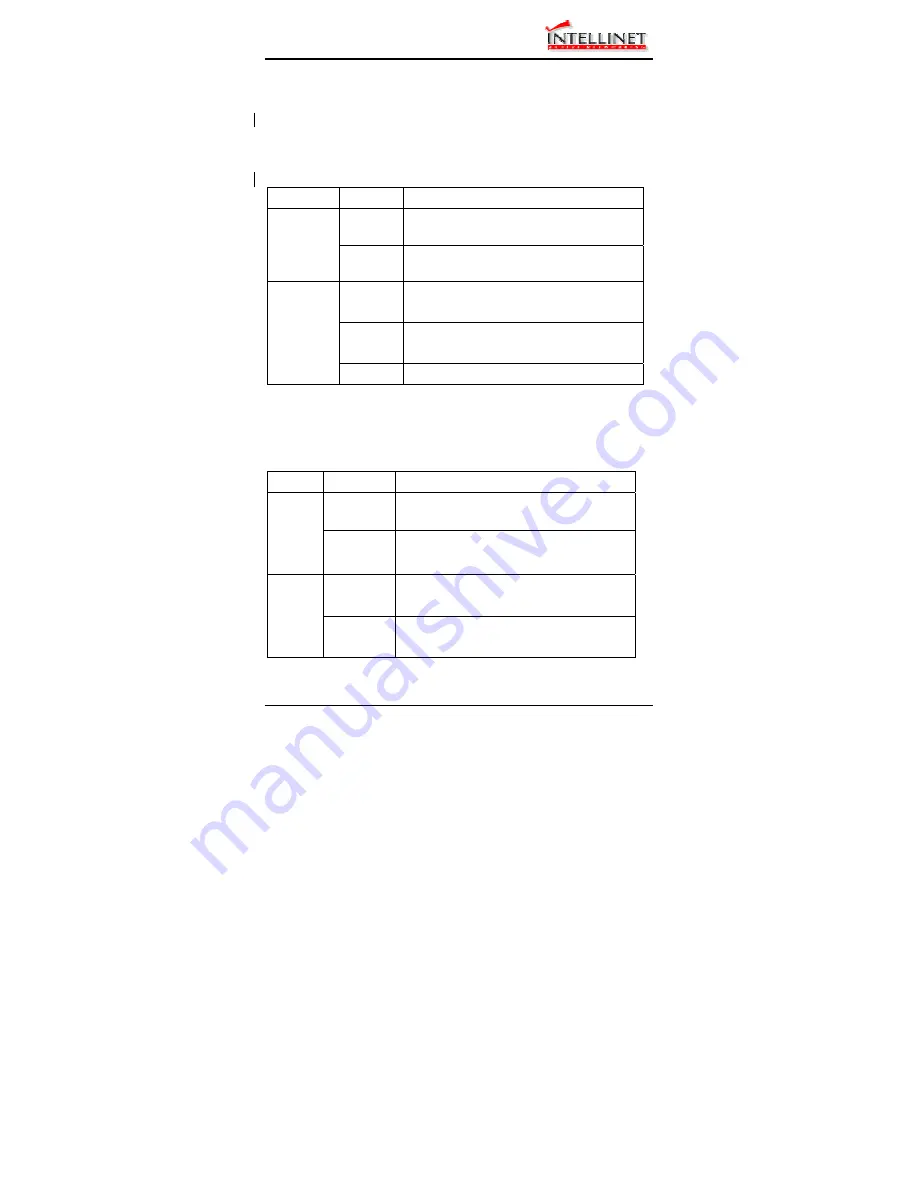
Port Status LEDs
The LEDs are located at the left side of each section, displaying status for
each respective port. Please refer to the following table for more details.
LED State
Indication
On
A valid network connection established.
LNK stands for LINK.
LNK/ACT
Flashing
Transmitting or receiving data.
ACT stands for ACTIVITY.
On
Connection in full duplex mode.
FDX stands for FULL-DUPLEX.
Flashing
Collision occurred.
COL stands for COLLISION.
FDX/COL
Off
Connection in half-duplex mode.
e
Gigabit Port Status LEDs
The LEDs are located at the left side of each Gigabit module, displaying
status for each respective port. Please refer to the following table for more
details.
LED State Indication
Flashing
Transmitting or receiving data.
ACT stands for ACTIVITY.
ACT
Off
No activity.
On
A valid network connection established.
LNK stands for LINK.
LNK
Off No
connection.


