Design Guide
91
Hub Interface
The values of R1, R2, R3, R4 and R5 must be rated at ± 1% tolerance. The selected resistor values
must also ensure that the reference voltage and reference swing voltage tolerance are maintained
over the input leakage specification. A 0.1 µF capacitor (C1 in
) should be placed within
0.5 inch of each resistor divider, and a 0.01 µF bypass capacitor (C2 in
) should be
placed within 0.25 inch of reference voltage pins. If the length of the trace from the voltage divider
to the pin is greater than 1 inch, place more than one 0.01 µF capacitor near the reference voltage
pin. The trace length from the voltage divider circuit to the HIREF and HUBREF pins must be no
longer than 3.5 inches.
Both the voltage reference and voltage swing reference signals should be routed at least 20 mils to
25 mils from all other signals.
7.3.3
Hub Interface 1.5 Resistive Compensation
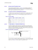
The hub interface uses a resistive compensation signal (RCOMP) to compensate buffer
characteristics for temperature, voltage, and process. The HIRCOMP resistor values are given in
shows the RCOMP_x circuits.
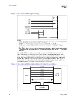
Figure 7-8. Hub Interface 1.5 Locally Generated Reference Divider Circuits
MCH
HISWNG_A
HIVREF_A
Intel
®
ICH3-S
0.35 V
0.35V
0.7 V
0.8 V
HITERM
HIREF
R4
R4
R5
R3
R2
R1
C2
C1
C1
C1
C1
C2
C2
C2
1.2V
1.8V
Table 7-9. Hub Interface 1.5 RCOMP Resistor Values
Component
Trace Impedance
RCOMP Resistor Value
RCOMP Resistor Tied To
MCH
50
Ω
± 10%
R1 = 24.9
Ω
± 1%
VCC1.2
ICH3-S
50
Ω
± 10%
R2 = 78.7
Ω
± 1%
VCC1.8
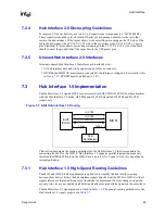
Figure 7-9. Hub Interface 1.5 RCOMP Circuits
R
1
1.2
V
MCH
HIRCOMP
R
2
1.8
V
Intel
®
ICH3-S
HICOMP
Содержание Xeon
Страница 24: ...Introduction 24 Design Guide This page is intentionally left blank ...
Страница 30: ...Component Quadrant Layout 30 Design Guide This page is intentionally left blank ...
Страница 34: ...Platform Stack Up and Component Placement Overview 34 Design Guide This page is intentionally left blank ...
Страница 52: ...Platform Clock Routing Guidelines 52 Design Guide This page is intentionally left blank ...
Страница 66: ...System Bus Routing Guidelines 66 Design Guide This page is intentionally left blank ...
Страница 118: ...Intel 82870P2 P64H2 118 Design Guide This page is intentionally left blank ...
Страница 146: ...I O Controller Hub 146 Design Guide This page is intentionally left blank ...
Страница 148: ...Debug Port 148 Design Guide This page is intentionally left blank ...
Страница 210: ...Schematic Checklist 210 Design Guide This page is intentionally left blank ...
Страница 220: ...Layout Checklist 220 Design Guide This page is intentionally left blank ...
Страница 222: ...Schematics 222 Design Guide This page is intentionally left blank ...


