background image

SRPL8 Server System  11 

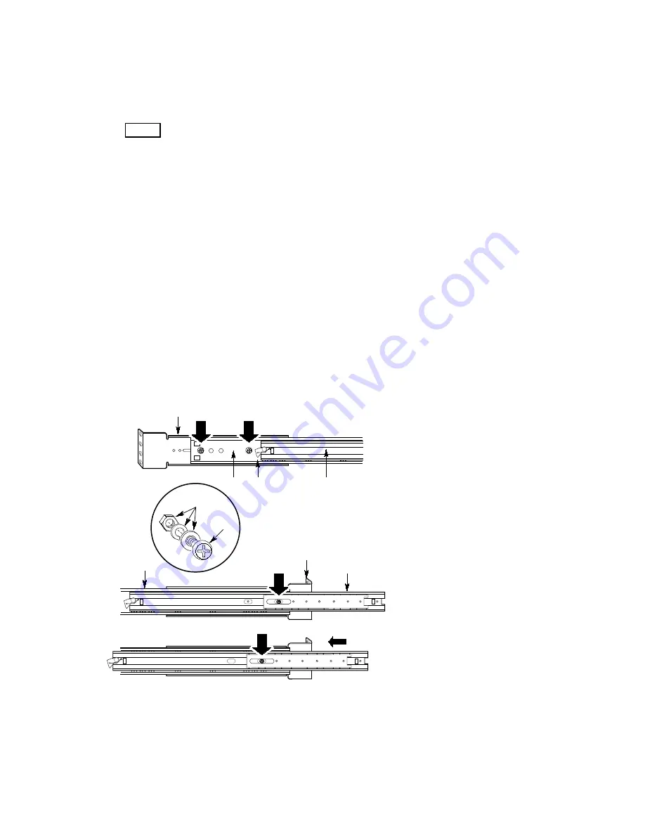
Attach the Center Bar and Large Outer Bar Assemblies to the 
Equipment Rack 

See Figure 7. 

1.  Orient a center bar and large outer bar assembly so that the flat side is facing toward the 

brackets attached to the vertical rails and the safety latch on the center bar is near the back of 
the rack. 

2.  Press the flat side of the outer bar into the U-shaped sections of the brackets.   
3.  Slide the assembly toward the front of the rack until the end of the outer bar is flush with the 

end of the U-shaped section of the front bracket. 

4.  Gently slide the center bar toward the front of the rack, and position the oblong slot in it over 

the first hole in the large outer bar.  Insert a screw through the hole in the bar and the first hole 
in the front bracket.  Place a lock washer and a nut on the screw, and loosely tighten it. 

5.  Position the oblong slot in the center bar over the third hole back from the front of the large 

outer bar.  Insert an 8-32 screw through the hole and the oblong slot in the front bracket.  Place 
a lock washer and an 8-32 nut on the screw, and loosely tighten it. 

6.  The back bracket has two holes and three slots in it.  This end of the outer bar has four holes in 

it.  Which holes and slots you use depend on the depth of the equipment rack.  After fitting the 
bar into the bracket, insert two screws through the holes in the bar and the appropriate oblong 
slots in the bracket.  Place a lock washer and a nut on each screw, and loosely tighten them. 

7.  Ensure that the brackets and bars are positioned correctly in the rack.  Then tighten all screws 

firmly (6.0 inch-pounds). 

OM11072

A

B

C

B

B

E

F

D

D

F

G

B

B


A.  Back right-angle extension bracket 
B. Screw 
C.  Flat washer, lock washer, and nut 
D.  Large outer bar 
E.  Safety latch on the center bar 
F. Center 

bar 

G.  Front right-angle extension bracket 

Figure 7.  Center Bar and Large Outer Bar Assembly 

Содержание SRPL8

Страница 1: ...RPL8 Server System Quick Start Guide Order Number A49446 001 How to do basic set up boot from the configuration software CD install the optional slide rail kit and access the Product Guide from the CD...

Страница 2: ...document This equipment has been tested and found to comply with the limits for a Class A digital device pursuant to part 15 of the FCC Rules These limits are designed to provide reasonable protection...

Страница 3: ...he Equipment Rack 11 Install the Server in the Rack 12 Check Power Cord 13 Power Cord Requirements 13 Connect Monitor Keyboard Mouse 15 Turn on Video Monitor and Server 16 Run Power on Self Test 18 Bo...

Страница 4: ...acking the server use only a mechanical assist unit to lift it off the shipping pallet The minimum server configuration weighs 51 kg 113 lbs the maximum weighs 63 5 kg 140 lbs Do not attempt to lift o...

Страница 5: ...ight 31 12 cm 12 25 inches 7u Width 44 45 cm 17 5 inches Depth 71 12 cm 28 0 inches Weight 51 4 kg 113 lbs minimum configuration 63 5 kg 140 lbs maximum configuration Required front clearance 10 inche...

Страница 6: ...within normal office environmental limits Select a site that meets these criteria Near a properly earthed grounded three pronged power outlet In the United States and Canada a NEMA 6 15R outlet for 2...

Страница 7: ...shock hazard you must include a third wire safety grounding conductor with the rack installation If a server power cord is plugged into an AC outlet that is part of the rack then you must provide pro...

Страница 8: ...using 3 of the 8 32 csink screws as shown in Figure 3 Figure 3 Slide Rail Mounting Screws 4 Fully extend the telescoping slide assembly until the center bar hits the safety latch on the small outer b...

Страница 9: ...uter bar assembly so that the center bar is facing up 9 Grasp the center bar with your right hand and the large outer bar with your left hand so that your left hand thumb is on the safety latch of the...

Страница 10: ...th the four mounting holes is facing toward the outside edge of the vertical rail 3 Position the bracket behind the mounting holes in the vertical rail OM11071 A D B C Figure 6 Right angle Bracket and...

Страница 11: ...n it 5 Position the oblong slot in the center bar over the third hole back from the front of the large outer bar Insert an 8 32 screw through the hole and the oblong slot in the front bracket Place a...

Страница 12: ...unit to lift it off the shipping pallet The minimum server configuration weighs 51 kg 113 lbs the maximum weighs 63 5 kg 140 lbs Use only a hand truck or other mechanical assist unit to move the serve...

Страница 13: ...power cord yet if you will be adding internal parts boards DIMMs removable media drives For these installation procedures see the Product Guide Power Cord Requirements Rating Cords must be rated for a...

Страница 14: ...beneath the external power connector three hexagonal pegs form a retention mechanism When you route the power cord between the hexagonal pegs the cord cannot be pulled accidentally from the back of th...

Страница 15: ...ators Item Feature Description A PCI add in board expansion slots B External LVDS connector C PS 2 compatible keyboard mouse port 6 pin D PS 2 compatible keyboard mouse port 6 pin E PS 2 compatible se...

Страница 16: ...ed 2 Remove drive protection card if present from the diskette drive 3 Turn on the video monitor 4 Plug the female end of the server AC power cord into the input receptacle on the back of the chassis...

Страница 17: ...n lit continuously it indicates an asserted fault status on one or more hard disk drives in the hot docking bay When flashing it indicates drive reset in progress H Front panel LCD Displays informatio...

Страница 18: ...a few seconds while the boot process continues and the system beeps once Then this message appears Operating System not found To create software installation diskettes see the printed Quick Start Gui...

Страница 19: ...the first boot device The server will therefore try to boot from diskette rather than from the CD ROM Even with the CD in the drive the server might continue to display Operating System Not Found Fol...

Страница 20: ...e sure the CD is in the drive and boot the server The Server Product Guide We provide the SRPL8 Server System Product Guide file on the CD Because printing from within Acrobat is time consuming we rec...

Страница 21: ...rmatted for your OS Instead you might see a message to the effect disk not formatted do you want to format it now Don t worry the drivers for YOUR OS are on the diskette and available to load on the s...

Страница 22: ...22 Quick Start Guide Warnings WARNING English AVERTISSEMENT Fran ais WARNUNG Deutsch AVVERTENZA Italiano ADVERTENCIAS Espa ol...

Страница 23: ...ch on the system 3 Unplug all AC power cords from the system or from wall outlets 4 Label and disconnect all cables connected to I O connectors or ports on the back of the system 5 Provide some electr...

Страница 24: ...at is Clean and free of airborne particles other than normal room dust Well ventilated and away from sources of heat including direct sunlight Away from sources of vibration or physical shock Isolated...

Страница 25: ...en position OFF bouton poussoir 3 D branchez tous les cordons d alimentation c a du syst me et des prises murales 4 Identifiez et d branchez tous les c bles reli s aux connecteurs d E S ou aux acc s d...

Страница 26: ...opre et d pourvu de poussi re en suspension sauf la poussi re normale Bien a r et loin des sources de chaleur y compris du soleil direct A l abri des chocs et des sources de vibrations Isol de forts c...

Страница 27: ...aus der Steckdose 4 Auf der R ckseite des Systems beschriften und ziehen Sie alle Anschlu kabel von den I O Anschl ssen oder Ports ab 5 Tragen Sie ein geerdetes Antistatik Gelenkband um elektrostatisc...

Страница 28: ...r normalen B roumgebung entwickelt Der Standort sollte Sauber und staubfrei sein Hausstaub ausgenommen gut gel ftet und keinen Heizquellen ausgesetzt sein einschlie lich direkter Sonneneinstrahlung ke...

Страница 29: ...ma 3 Togliere tutte le spine dei cavi del sistema dalle prese elettriche 4 Identificare e sconnettere tutti i cavi attaccati ai collegamenti I O od alle prese installate sul retro del sistema 5 Qualor...

Страница 30: ...una postazione che sia Pulita e libera da particelle in sospensione a parte la normale polvere presente nell ambiente Ben ventilata e lontana da fonti di calore compresa la luce solare diretta Al ripa...

Страница 31: ...S o a los puertos situados en la parte posterior del sistema 5 Cuando manipule los componentes es importante protegerse contra la descarga electrost tica ESD Puede hacerlo si utiliza una mu equera ant...

Страница 32: ...instrucciones del fabricante El sistema est dise ado para funcionar en un entorno de trabajo normal Escoja un lugar Limpio y libre de part culas en suspensi n salvo el polvo normal Bien ventilado y al...

Страница 33: ......

Страница 34: ...34 Quick Start Guide...

Отзывы: