Intel
®
Server System SR1690WB Service Guide
15
Back Panel Connectors
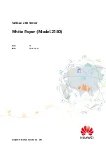
Figure 7. Back Panel Connectors
The NIC LEDs at the right and left of each NIC provide the following information.
A.
NIC1 connector with USB
ports 2, 5
B.
USB ports 8, 9
C.
NIC2 connector
D.
RJ-45 Serial B port
E.
Internal Video Connector
AF003217
A
B
C
D
E
Table 3. NIC LED Descriptions
LED
LED
State
LED State
Description
NIC1/
NIC2
Left
LED
Off
No network connection
Solid Amber
Network connection in place
Blinking Amber
Transmit/receive activity
Right
LED
Off
10 Mbps connection (if left
LED is on or blinking)
Solid Amber
100 Mbps connection
Solid Green
1000 Mbps connection
Содержание SR1690WB - Server System - 0 MB RAM
Страница 6: ...vi Intel Server System SR1690WB Service Guide...
Страница 14: ...xiv Intel Server System SR1690WB Service Guide...
Страница 18: ...xviii Intel Server System SR1690WB Service Guide...
Страница 102: ...84 Intel Server System SR1690WB Service Guide...
Страница 122: ...104 Intel Server System SR1690WB Service Guide...
Страница 128: ...110 Intel Server System SR1690WB Service Guide...
Страница 149: ...Intel Server System SR1690WB Service Guide 131 Intel Intel Intel Web UL...
Страница 150: ...132 Intel Server System SR1690WB Service Guide ITE ITE 5V...
Страница 151: ...Intel Server System SR1690WB Service Guide 133...
Страница 152: ...134 Intel Server System SR1690WB Service Guide ESD ESD ESD ESD ESD...
Страница 153: ...Intel Server System SR1690WB Service Guide 135...
Страница 154: ...136 Intel Server System SR1690WB Service Guide...