


Hot Swap Drive Cage Upgrade Install Instructions (optional)
Intel® Entry Server Chassis SC5299-E UP/DP/WS/BRP User Guide
79
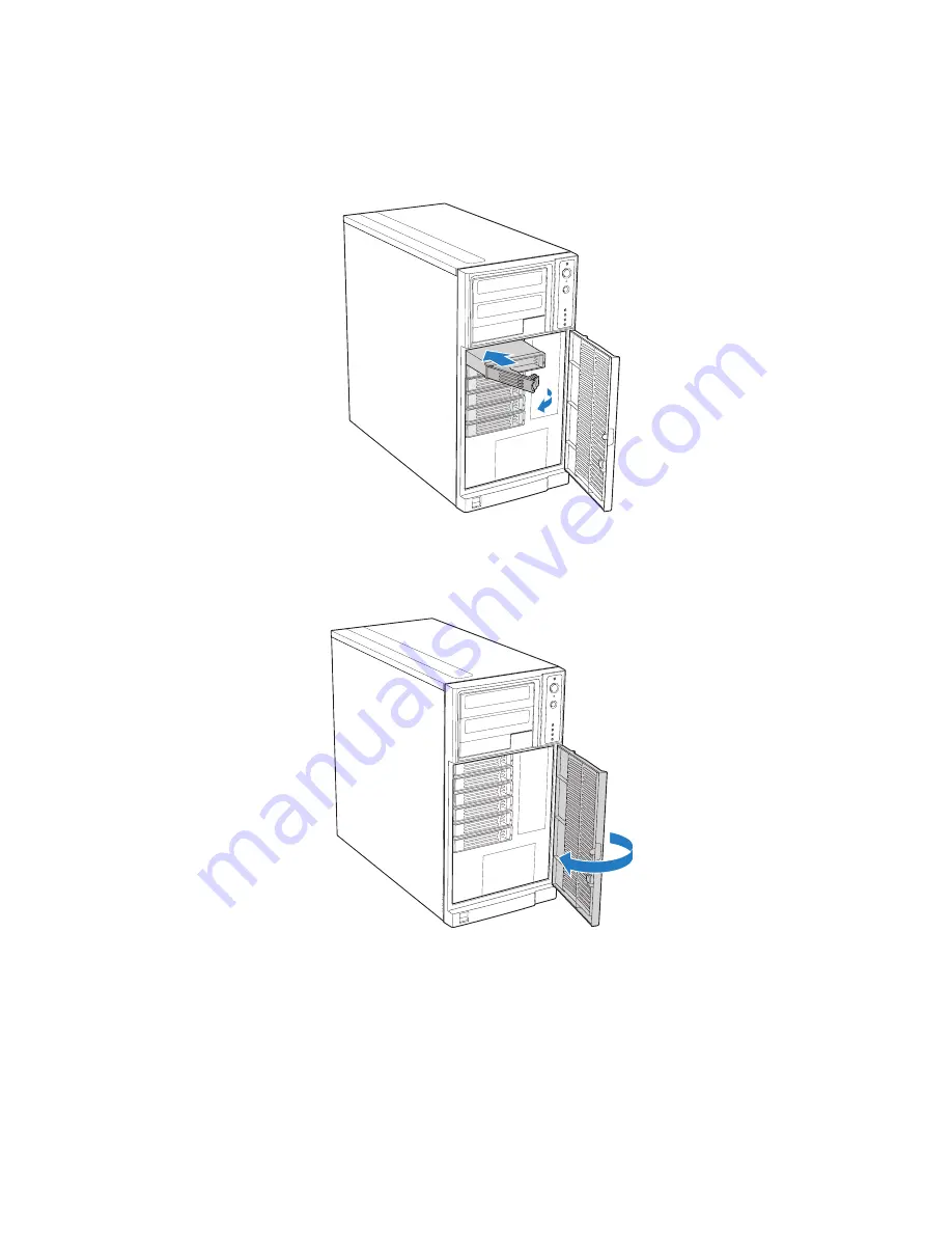
Note:
For proper airflow, the drive carrier must be replaced in the chassis, even if no hard drive
is installed in it.
Figure 101. Re-installing Drive Carrier in Hot Swap Drive Cage
6. Close the drive bay access door.
Figure 102. Closing Drive Bay Access Door
AF000313
AF000314
Содержание S3210SHLC - Entry Server Board Motherboard
Страница 8: ...Preface viii Intel Entry Server Chassis SC5299 E UP DP WS BRP User Guide...
Страница 16: ...xvi Intel Entry Server Chassis SC5299 E UP DP WS BRP User Guide...
Страница 18: ...xviii Intel Entry Server Chassis SC5299 E UP DP WS BRP User Guide...
Страница 30: ...Server Chassis Features 12 Intel Entry Server Chassis SC5299 E UP DP WS BRP User Guide...
Страница 78: ...Hardware Installations and Upgrades 60 Intel Entry Server Chassis SC5299 E UP DP WS BRP User Guide...
Страница 110: ...Rack Mount Kit Install Instructions optional 92 Intel Entry Server Chassis SC5299 E UP DP WS BRP User Guide...
Страница 114: ...Technical Reference 96 Intel Entry Server Chassis SC5299 E UP DP WS BRP User Guide...
Страница 138: ...Safety Information 120 Intel Entry Server Chassis SC5299 E UP DP WS BRP User Guide I nt el I nt el I nt el Web UL...
Страница 139: ...Safety Information Intel Entry Server Chassis SC5299 E UP DP WS BRP User Guide 121 ITE ITE 5V...
Страница 140: ...Safety Information 122 Intel Entry Server Chassis SC5299 E UP DP WS BRP User Guide...
Страница 141: ...Safety Information Intel Entry Server Chassis SC5299 E UP DP WS BRP User Guide 123 ESD ESD ESD ESD ESD...
Страница 142: ...Safety Information 124 Intel Entry Server Chassis SC5299 E UP DP WS BRP User Guide...
Страница 154: ...Installation Assembly Safety Instructions 136 Intel Entry Server Chassis SC5299 E UP DP WS BRP User Guide...
Страница 158: ...Getting Help 140 Intel Entry Server Chassis SC5299 E UP DP WS BRP User Guide...
Страница 166: ...Warranty 148 Intel Entry Server Chassis SC5299 E UP DP WS BRP User Guide...
Страница 174: ...Regulatory and Compliance Information 156 Intel Entry Server Chassis SC5299 E UP DP WS BRP User Guide...


