Intel
®
Server System R1000WF Product Family System Integration and Service Guide
50
3.6
OCP Expansion Module – Installation / Removal
3.6.1
OCP Expansion Module Installation
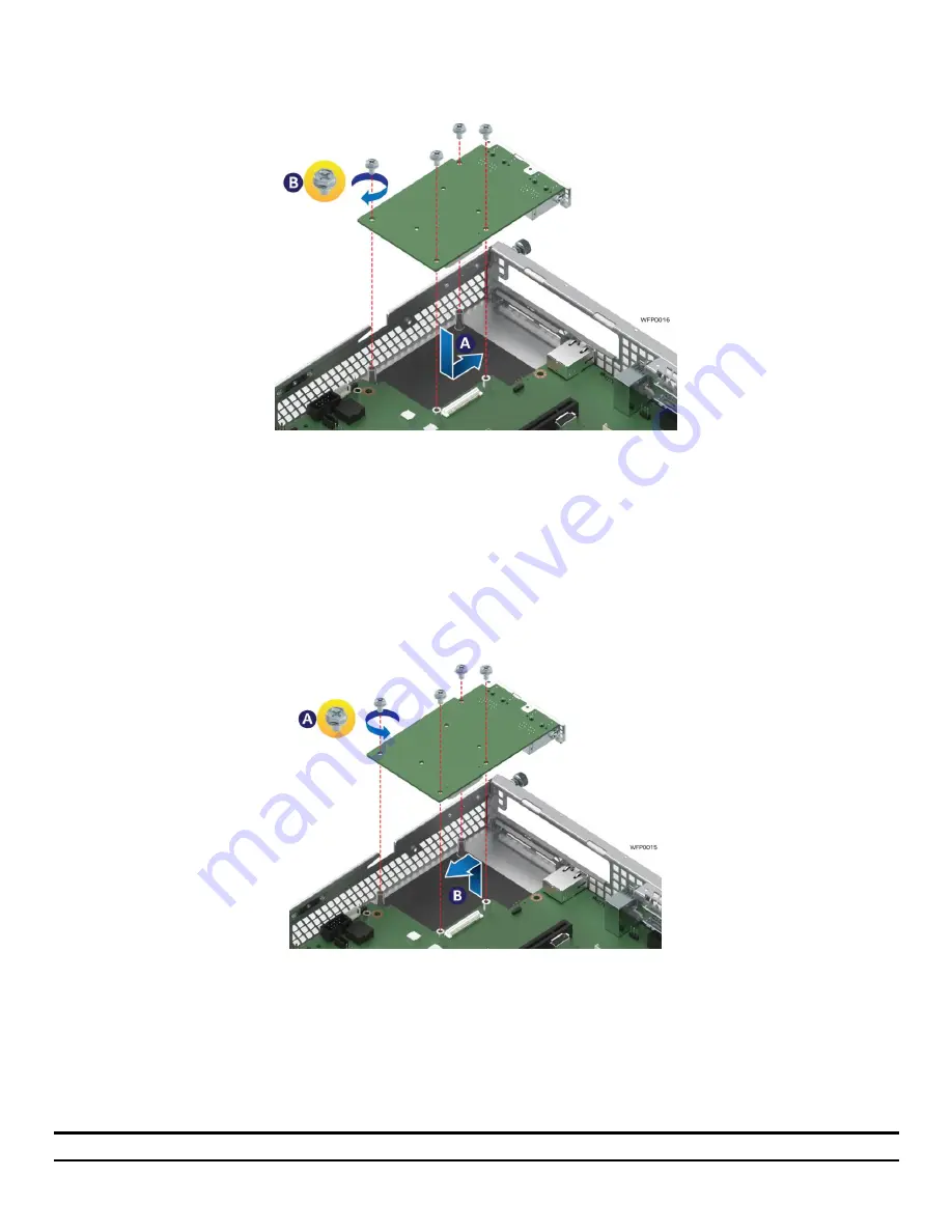
Figure 73. Installing OCP Expansion Module
1.
Remove the OCP bay filler from the chassis back panel. Squeeze the panels on each side of the filler and
push it out from the chassis.
2.
Carefully angle and insert the rear connectors of the OCP module into the cut-out on the chassis back
panel and position the module over the server board connector. Care should be taken NOT to damage
the I/O shield material when placing the OCP module into the back panel cut-out (see Letter ‘A’).
3.
Carefully press down on the module to engage the connectors.
4.
Secure the module with four screws as shown (see Letter ‘B’).
3.6.2
OCP Expansion Module Removal
Figure 74. Removing an OCP Expansion Module
1.
Power off the server and detach the power cable(s).
2.
Detach all cables from the OCPModule.
3.
Remove the system cover – (see Section 2.2.1).
4.
Remove the four (4) screws as shown (see Letter ‘A’).
5.
Carefully pull up on the OCP Module until it disengages from the server board (see Letter ‘B’).
6.
If no replacement module is to be installed, re-install the OCP bay filler panel.
Note:
The filler panel snaps into the back panel from the outside of the chassis.
Содержание R1000WF Series
Страница 2: ...Intel Server System R1000WF Product Family System Integration and Service Guide Blank Page ...
Страница 16: ......


