4
General Installation Process
6
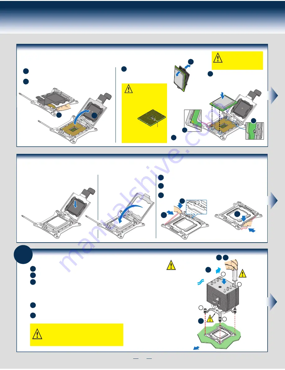
Install Heat Sink(s)
Get heat sink from the shipping position.
A
Remove the protective film on the TIM if present.
E
D
B
C
Securely re-tighten each fastener again in the same order as performed in Step E.
Using a #2 Phillips* screwdriver, finger-tighten each fastener diagonally,
according to the numbers shown.
Align heat sink fins to the front and back of the chassis for correct airflow.
Airflow goes from front-to-back of chassis.
The heat sink has four captive fasteners and should be tightened using the following procedure:
CAUTION: The heat sink has thermal interface
material (TIM) on the underside of it. Use caution so
that you do not damage the thermal interface material.
Use gloves to avoid sharp edges.
OPEN
1st
CLOS
E 1st
C
TIM
Processor
Soc
ket
AIRFLOW
B
2
3
1
4
Chassis Front
D E
CAUTION:
Do not
over-tighten
fasteners.
Save the
protective
cover.
Install the Processor(s) ... continued
D. Remove the Cover
Press the cover to
remove it.
Carefully lower the load plate over
the processor.
E. Close the Load Plate
Push down on the locking lever on the
CLOSE 1st
side.
F. Latch the Locking Lever
A
B
Slide the tip of the lever under the notch in the load plate.
Make sure
the load plate tab engages under the socket lever when fully closed.
C
Repeat the steps to latch the locking lever on the other side.
OPEN
1st
CLOS
E 1st
REM
OVE
REM
OVE
CLOS
E 1st
B
A
OPEN
1st
CLOS
E 1st
C
NOTE: Latch the levers in
the order as shown.
Install the Processor(s) ... continued
B
OPEN
1st
CLOSE
1st
A
NO CPU
B. Open the Load Plate
A
B
Open the load plate all the way.
Press the locking lever slightly to raise the
load plate.
B
C
C. Install the Processor
Take the processor out of the
box and remove the
protective shipping cover.
CAUTION: When unpacking
a processor, hold by the
edges only to avoid touching
the gold contact pins.
Save the
protective
cover.
A
CAUTION: The underside
of the processor has
components that may damage
the socket pins if installed
improperly.
Processor must
align correctly
with the
socket
opening before
installation.
DO NOT DROP
processor into socket!
Components
Note location of gold key at
corner of processor.
A
B
C
Orient the processor with the socket so
that the processor cutouts match the
four orientation posts on the socket.
Содержание P4208CP4MHGC
Страница 2: ...This page is intentionally left blank...
Страница 17: ...G43150 001...


