background image

Development Tools User’s Manual  

67

IXP2400/IXP2800 Network Processors

Developer Workbench

2.9.5

IXP2400 CBUS Connections

After you have configured the packet simulation with devices and ports and created or imported 
data streams, you need to specify the connections to the media/switch fabric for each chip in your 
project.

1. On the 

Simulation

 menu, click 

System Configuration

, then click the 

CBUS Connections 

tab. 

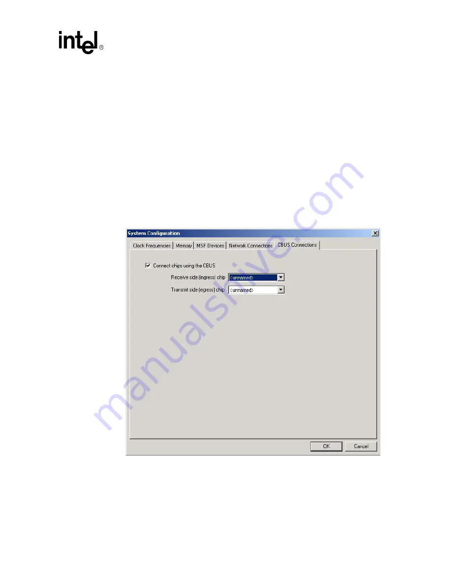
The CBUS 

Connections

 property page appears. The page contains a check box to enable 

connections using the CBUS. When you select 

Connect using the CBUS

 the receive (ingress) 

and transmit (egress) pull down boxes are active.

2. Select the chip to which you want to make connections in the pull down boxes.

3. When you have finished click 

OK

.

Figure 13

 displays the CBUS Connections property page.

Figure 13. CBUS Connections Property Page - IXP2400

Содержание IXP2400

Страница 1: ...Intel IXP2400 IXP2800 Network Processors Development Tools User s Guide March 2004 Order Number 278733 011 ...

Страница 2: ...tion assumes no responsibility or liability for any errors or inaccuracies that may appear in this document or any software that may be provided in association with this document Except as permitted by such license no part of this document may be reproduced stored in a retrieval system or transmitted in any form or by any means without the express written consent of Intel Corporation Contact your ...

Страница 3: ... 25 2 3 1 Creating a New Project 25 2 3 1 1 Debug only Projects 27 2 3 2 Opening a Project 28 2 3 3 Saving a Project 28 2 3 4 Closing a Project 29 2 3 5 Specifying a Default Project Folder 29 2 4 About the Project Workspace 30 2 4 1 About FileView 30 2 4 2 About ThreadView 31 2 4 2 1 Expanding and Collapsing Thread Trees 31 2 4 2 2 Renaming a Thread 31 2 4 3 About InfoView 32 2 5 Working with File...

Страница 4: ...ile 50 2 7 2 6 Selecting the Target obj File 50 2 7 2 7 Deleting a Target list or obj File 51 2 7 2 8 Selecting Compile Options 51 2 7 2 9 Saving Build Settings 53 2 7 3 Invoking the Compiler 53 2 7 4 Compilation Errors 53 2 8 The Linker 54 2 8 1 Customizing Linker Settings 54 2 8 2 Building and Rebuilding a Project 57 2 9 Configuring the IXP2400 Simulation Environment 58 2 9 1 IXP2400 Clock Frequ...

Страница 5: ...Using Imported Variable Data 111 2 13 4 Exporting the Startup Script 113 2 13 5 Changing Hardware Options 113 2 13 5 1 Specifying Hardware Startup Options 113 2 13 6 The Command Line Interface 114 2 13 7 Command Scripts 114 2 13 8 Thread Windows 115 2 13 8 1 Controlling Thread Window Activation 115 2 13 8 2 Thread Window Controls 117 2 13 8 3 Tracking the Active Thread 119 2 13 8 4 Running to Curs...

Страница 6: ...anging a Memory Watch 146 2 13 13 5 Changing the Memory Watch Address Radix 146 2 13 13 6 Changing the Memory Watch Value Radix 147 2 13 13 7 Depositing Memory Data 147 2 13 14 Execution Coverage 147 2 13 14 1 Changing Execution Count Ranges and Colors 149 2 13 14 2 Displaying and Hiding Instruction Addresses 149 2 13 14 3 Instruction Markers 149 2 13 14 4 Miscellaneous Controls 150 2 13 14 5 Scal...

Страница 7: ...ling Considerations 186 3 4 4 Event Selection Dialog Box 186 3 5 Output Formats 187 4 Assembler 189 4 1 Assembly Process 189 4 1 1 Command Line Arguments 189 4 1 2 Assembler Steps 191 4 1 3 Case Sensitivity 192 4 1 4 Assembler Optimizations 192 4 1 5 Processor Type and Revision 192 5 Microengine C Compiler 193 5 1 The Command Line 193 5 2 Supported Compilations 193 5 3 Supported Option Switches 19...

Страница 8: ..._meReg 211 6 7 2 13 uof_neighReg 212 6 7 2 14 uof_neighRegTab 212 6 7 2 15 uof_importExpr 212 6 7 2 16 uof_impExprTabTab 212 6 7 2 17 uof_xferReflectTab 212 6 7 2 18 uof_UcVar 212 6 7 2 19 uof_ucVarTab 212 6 7 2 20 uof_initRegSymTab 213 6 7 2 21 uof_uwordFixup 213 6 7 2 22 uof_codeArea 213 6 8 DBG_OBJS 213 6 8 1 Debug Objects Header 213 6 8 2 Debug Object Chunk Header 214 6 8 3 DBG_STRT 214 6 8 4 ...

Страница 9: ...or 229 8 1 Overview 229 8 2 Invoking the Transactor 230 8 3 Transactor Commands 231 8 3 1 define 232 8 3 2 undef 233 8 3 3 233 8 3 4 benchmark 234 8 3 5 cd 234 8 3 6 close 234 8 3 7 connect 234 8 3 8 deposit 235 8 3 9 dir 236 8 3 10 examine 236 8 3 11 exit 237 8 3 12 force 237 8 3 13 foreign_model 238 8 3 14 go 239 8 3 15 go_thread 239 8 3 16 gop 239 8 3 17 goto 239 8 3 18 goto_addr 240 8 3 19 hel...

Страница 10: ... 1 4 FOR_MOD_EXIT 257 9 1 5 FOR_MOD_RESET 258 9 1 6 FOR_MOD_DELETE 258 9 2 Overview of XACT API Functions 258 9 3 State Name Reference Routines 260 9 3 1 XACT_find_wildcard_state_name 260 9 3 2 XACT_get_handle 261 9 3 3 XACT_delete_handle 261 9 3 4 XACT_get_state_info 261 9 3 5 XACT_get_state_value 262 9 3 6 XACT_get_state_field 262 9 3 7 XACT_get_array_state_value 262 9 3 8 XACT_set_state_value 2...

Страница 11: ... 9 5 3 XACT_printf 268 9 5 4 XACT_printf_error 268 9 5 5 XACT_register_console_function 268 9 5 6 XACT_register_console_function_w_arrayed_args 269 9 5 7 XACT_unregister_console_function 269 9 5 8 XACT_ExecuteCommandStr 269 9 5 9 XACT_init_gui_console 270 9 5 10 XACT_gui_execute_command 270 9 5 11 XACT_start_console 270 9 5 12 XACT_initialize 270 9 5 13 XACT_stop_execution_at_clk 270 9 5 14 XACT_e...

Страница 12: ...297 C 1 6 Additional CMB_IO API 298 C 1 7 cmbRead32 cmbWrite32 298 C 1 8 cmbSetCb 299 C 1 9 cmbSwapRead32 cmbSwapWrite32 299 C 1 10 cmbBFMRead32 cmbBFMWrite32 300 C 2 ENUMs 301 C 3 Defines 301 D PCI Bus Functional Model 303 D 1 Loading the BFM 303 D 2 Initializing the BFM 303 D 3 Creating a Device 303 D 4 Calling Console Functions from Another Foreign Model 304 D 5 Setting a Callback Function 304 ...

Страница 13: ...perty Page IXP2400 67 14 Clock Frequencies for the IXP2800 69 15 IXP2800 Memory Options 70 16 IXP2800 MSF Devices 71 17 The Create Media Bus Device Dialog Box for SPI 4 72 18 The Create Media Bus Device Dialog Box for CSIX 73 19 Port Characteristics Edit Port Dialog Box 75 20 Network Connections Property Page IXP2800 76 21 CBUS Connections Property Page IXP2800 77 22 Packet Simulation Options Prop...

Страница 14: ...ampling 174 56 TBS Window Sampling 175 57 Random Based Sampling 175 58 Canned Analysis Property Page 177 59 Time Based Sampling Property Page 179 60 Random Based Sampling Property Page 181 61 Sampling Macros 183 62 Monitor Sampling Macro 184 63 Threshold Sampling Macro 185 64 Event Selection Dialog Box 187 65 Assembly Process 191 66 Compilation Steps 198 67 Example of Foreign Model Usage 221 Table...

Страница 15: ...bench Shortcuts Files 289 6 Developer Workbench Shortcuts Projects 290 7 Developer Workbench Shortcuts Edit 290 8 Developer Workbench Shortcuts Bookmarks 291 9 Developer Workbench Shortcuts Breakpoints 291 10 Developer Workbench Shortcuts Builds 292 11 Developer Workbench Shortcuts Debug 292 12 Developer Workbench Shortcuts Run Control 292 13 Developer Workbench Shortcuts View 293 ...

Страница 16: ......

Страница 17: ...A Transactor States Describes the Transactor internal states Appendix B Developer Workbench Shortcuts Contains a listing and description of commonly used shortcuts Appendix C Intel XScale Core Memory Bus Functional Model Describes the Intel XScale Bus Functional Model Appendix D PCI Bus Functional Model Describes the PCI Bus Functional Model Appendix E SPI4 Bus Functional Model Describes the SPI4 ...

Страница 18: ...IXP2400 IXP2800 Microengine C Compiler LIBC Library Reference Manual Contains a modified subset of standard C Library functions supported on the IXP2400 and IXP2800 Network Processors Intel IXP2400 Network Processor Hardware Reference Manual Contains detailed hardware technical information about the IXP2400 Network Processor for designers Intel IXP2800 Network Processor Hardware Reference Manual C...

Страница 19: ...imulation with local foreign models in which the Workbench the Transactor and one or more foreign model Dynamic Link Libraries all run on the same Windows platform Local simulation with a remote foreign model in which the Workbench and the Transactor both run on the same Windows platform and communicate over the network with a foreign model running on a remote system Hardware in which the Workbenc...

Страница 20: ...Section 2 2 2 Customize toolbars and menu bars see Section 2 2 3 Save and restore GUI customizations see Section 2 2 3 6 2 2 1 About Windows Toolbars and Menus Dockable windows contain controls and data You can attach them to a location on the Workbench main window or you can float them over the main window All toolbars and menu bars are dockable See Figure 2 To float or undock a window or toolbar...

Страница 21: ...ifferent windows such as going to the Window menu and selecting the window cascading the windows using the button and selecting with the mouse pointer pressing CTRL F6 to switch from one window to the next Removing the tabs gives you more workspace in the windows Project Workspace See Section 2 4 Output Window This window displays the results of Find in Files assembly and compile results build res...

Страница 22: ...ine Clock The present cycle count of the Microengine clock simulation debug mode only In hardware debug mode it shows stopped or running to indicate microengine state Text Insertion Point The location of the text insertion point cursor by line and column Read only Write The Read Write status of the selected file If READ is dimmed the status is Read Write 2 2 3 Customizing Toolbars and Menus You ca...

Страница 23: ...ck the Toolbars tab 3 Select the toolbar to delete in the Toolbars list 4 Click Delete Note You cannot delete the GUI s default toolbars Menu bar File Debug Build Edit View 2 2 3 4 Adding and Removing Toolbar Buttons and Controls To customize the buttons on the toolbars 1 On the Tools menu click Customize The Customize dialog box appears 2 Click the Commands tab 3 From the Categories list select a...

Страница 24: ...k Menu in the Commands box All the menus appear in the Buttons box c Select a menu and drag it to the main menu bar That menu then becomes a new menu on the main menu bar Menus on Toolbars To put a menu on a toolbar 1 In the Customize dialog box click the Commands tab 2 Click Menu in the Categories box All the menus appear in the Buttons box 3 Drag any menu to any toolbar Note You can put your mos...

Страница 25: ... is maintained in a Developer Workbench project file dwp A debug only project is one in which the user specifies an externally built uof file for each chip in the project If a project is created as debug only the user does not specify assembler and compiler source files manage build settings or perform uof file builds using the Workbench GUI When you start the workbench you can Create a new projec...

Страница 26: ...ore than one chip they must all have unique names You cannot add a second chip until you have named the first chip When you finish creating a project you cannot change the number of chips in it To rename a chip select the chip in the list and click Rename The Chip Name dialog box appears Type the chip s name and click OK To add a chip to the configuration click Add The Chip Name dialog box appears...

Страница 27: ...tion Specify Debug only UOF files The Project Workspace Fileview tab does not display the tree elements Assembler Source Files Compiler Source Files or Macros since the Workbench does not associate source files with the Debug only project Select Specify Debug only UOF Files from the Project menu When you select the Debug only option the dialog box shown in Figure 3 is used to specify the uof file ...

Страница 28: ... projects opened 1 On the File menu click Recent Projects 2 Click the project file from the list Note Opening a project automatically closes the currently open project if any after asking you if you want to save changes if there are any 2 3 3 Saving a Project To save a modified project On the File menu click Save Project This saves all project configuration information such as debug settings to th...

Страница 29: ...osing the project An open project is automatically closed whenever you open another project or create a new project 2 3 5 Specifying a Default Project Folder You can specify a default folder for creating new projects and opening projects When you select Default Project Folder from the File menu the Browse for folder dialog box appears The default project folder is used as the initial folder in the...

Страница 30: ...ThreadView is disabled To toggle the visibility of the Project Workspace On the View menu select or clear Project Workspace or Click the button on the View toolbar 2 4 1 About FileView FileView contains a tree listing your project files The top level item in the tree is labeled project name files There are four second level folders Assembler Source Files which expands to an alphabetical list of al...

Страница 31: ...ch Microengine item expands to list the four or eight threads in a Microengine but only if the threads are active in the microcode If a Microengine is not loaded with code no sign appears to the left of the icon and therefore cannot be expanded to show the threads By default a chip s threads are named Thread 0 through Thread n The last thread by default varies depending on which network processor ...

Страница 32: ... files see Section 2 5 5 Save all files at once see Section 2 5 6 Print files see Section 2 5 8 Insert files into a project see Section 2 5 9 Remove files from a project see Section 2 5 9 Edit a file see Section 2 5 10 Bookmarks error tags see Section 2 5 11 See also Working with File Windows see Section 2 5 7 About Find in Files see Section 2 5 12 About Fonts and Syntax colors see Section 2 5 13 ...

Страница 33: ...k Close or On the Window menu click Close to close the active file and its document window or On the Windows menu click Close All to close all open files and their document windows Note All files that have been edited but not saved are automatically saved when you perform any operation which uses file data such as assembling building updating dependencies and finding in files 2 5 4 Saving Files To...

Страница 34: ...x If you select All files you must include the extension in the name 2 5 6 Saving All Files at Once You can save all modified files in your project at once To do this On the File menu click Save All or Click the button on the File toolbar 2 5 7 Working With File Windows When you select a file text Assembler source Compiler source source header or script for viewing or editing it appears in a file ...

Страница 35: ...Setting Up the Printer 1 On the File menu click Printer Setup The Print Setup dialog box appears 2 Select the printer properties for your printer They will vary depending on the printer you select in the Name box 3 Click OK when done Setting the printer properties does not print the file To do this see Section 2 5 8 2 2 5 8 2 Printing the File You can print text files to a hardcopy printer or to a...

Страница 36: ...o remove a file from your project 1 In the Project Workspace click the File View tab 2 Right click the file that you want to delete 3 Click Delete on the shortcut menu or Select the file and then press the DELETE key Note The file is removed from the project but it is not deleted from the disk 2 5 10 Editing Files The Workbench editor is similar to standard text editors See Table 7 on page 290 for...

Страница 37: ...ing directly to a specified line within an opened document or thread window If the user selects Go To from the Edit menu the dialog shown in Figure 5 appears The user enters the desired line number and clicks Go To The insertion cursor in the document or thread window that currently has focus is moved to the beginning of the specified line and the window is scrolled so that the specified line is v...

Страница 38: ...e searched or select from a predefined list of file types in the In files file types list This box acts as a filter on the names of files to be searched For example you can specify foo txt to search only files with names that begin with foo and have an file extension of txt 4 Type the name of the folder to be searched in the In folder box or select from the list of previously searched folders in t...

Страница 39: ...ce is selected In all cases the window containing the file is automatically put on top of the document windows If the file isn t already open it is automatically opened The line containing the occurrence is marked with a blue arrow 2 5 13 About Fonts and Syntax Coloring Source files that is those with file extensions of uc c or h appear with syntax coloring of keywords and comments Keywords are wo...

Страница 40: ...e folder The Workbench Creates these folders when you open a project Updates them when An edited source file is saved A source file is inserted into or deleted from the project or You update dependencies by selecting Update Dependencies from the Project menu To go to the location in the source file where a macro is defined double click the macro name If an opened source file contains a macro refer...

Страница 41: ...rkspace root files are distinguished by having an to the left of it You can designate the same output file to be loaded into more than one Microengine You can also include the same source file under more than one root file making the file a descendant of multiple root files In order for the Workbench to build list and image files you must assign a list file to at least one Microengine You set root...

Страница 42: ... specify a range of revisions for which you want your microcode assembled Section 4 1 5 covers this topic in more detail Do the following 1 On the Build menu click Settings The Build Settings dialog box appears 2 Click the General tab 3 Select the range of processor revisions on which you want the linked code to run Note Select from the Minimum revision and the Maximum revision lists If you select...

Страница 43: ...fy Assembler options do the following 1 On the Build menu click Settings The Build Settings dialog box appears 2 Click the Assembler tab The list File The Output to target list file list allows you to select a list file from the set of list files that are currently defined in the project All other controls on the page are updated according to which list file you select in the list Insert file 1 On...

Страница 44: ...igned byte address which specifies the start of the region If Size is unchecked then the region begins at the start address and extends to the end of local memory If Size is checked then the region begins at the start address and extends for the number of bytes specified in the Size field Produce Debug Information Select Produce debug info to add debug information to the output file If you do not ...

Страница 45: ... Build Settings dialog box works with a copy of the build settings in the project When you click OK the Workbench validates your data and does not allow the dialog box to close if there are any errors Validation is independent of which page is active at the time You have the option to fix the errors or click Cancel if you choose not to save any changes you have made When the data in Build Settings...

Страница 46: ...w Do any of the following to display the line of source code that caused an error Double click the error description or Press F4 or Click the button If no error is selected the first error becomes selected If the last error is selected then no error is selected To go to the source line for the previous error Press SHIFT F4 or Click the button If no error is selected then the last error becomes sel...

Страница 47: ...4 Opening C source files see Section 2 5 2 Editing C source files see Section 2 5 10 Closing a C source file see Section 2 5 3 Searching for text in a C source file see Section 2 5 10 and Section 2 5 12 Fonts and syntax colors in a C source file see Section 2 5 13 This section details Adding C source files to your project see Section 2 7 1 Selecting the target list file see Section 2 7 2 2 Selecti...

Страница 48: ...statements in C source code files This control displays a list of paths with a GUI for typing in or editing of directory paths or browsing to directories to be added to the list The GUI also provides the means for deleting or changing the search order of the paths Regardless of whether the path information is entered in an absolute or relative format it is automatically converted to a relative for...

Страница 49: ...ng the absolute path of the target list file If this path is not correct click New again and select a new path 2 7 2 3 Selecting C Source Files to Compile The C Compiler in the Workbench can compile one or more C source files into one list file You must select the source files that you want to compile To do this 1 In the Build Settings dialog box click the Compiler tab 2 Click Choose source files ...

Страница 50: ... file 1 Click the desired file in the Source files to compile list 2 Click the button This removes the file from the compilation but not from the project 2 7 2 6 Selecting the Target obj File You can compile your C source file to create an obj file rather than a list file To do this 1 In the Build Settings dialog box click the Compiler tab 2 Click New obj file The Compiler obj target dialog box ap...

Страница 51: ... Determines the region in local memory where the Compiler can allocate variables The region starts at the address you specify and extends to the end of local memory Spill sequence Determines the algorithm used by the Compiler for spilling register contents to memory Inlining None No inlining is done including functions explicitly tagged in the source code with the inline specifier Explicit default...

Страница 52: ...ler at the expense of the project not being debuggable in any fashion through the Workbench Produce assembler source file Select Produces an assembly code file uc Clear default Does not produce an assembly code file Allow mixed C and assembler source files Select Allows the user to select both C and MicroCode project files instead of only C files The compiler is invoked with the uc switch to indic...

Страница 53: ...ady open activate its document window by clicking on the file window 2 On the Build menu click Compile or Press CNTRL SHIFT F7 or Click the button on the Build toolbar Results The results of an assembly appear in the Build tab of the Output window which automatically appears You can control the amount of detail provide in the results On the Build menu select Verbose Output to display detailed resu...

Страница 54: ... for the Linker and directing the packaging of one or more Microengine specific list files into a uof file Each chip has several Microengines that can each be loaded with execution code according to the list file selected for that Microengine You can also specify the assembly options by clicking the Assembler tab and the C Compiler tab in the Build Settings dialog box Chip The Chip box contains a ...

Страница 55: ...ngines you get an error Produce debug information Select Produce debug info to add debug information to the output file If you do not select this option you will not be able to open a thread window in debug mode Note The Produce debug info switch must be set for the necessary debug information to be present in the uof file Unchecking the Produce debug info check box causes the size of the uof file...

Страница 56: ...starting at the base address allocating as much memory as needed up to the Scratch offset size for variables Scratch segment size bytes The Scratch segment size is a parameter sent to the Linker The Linker reserves as much scratch memory as necessary for variables up to the segment size SRAM offset The SRAM offset is a parameter sent to the Linker The Linker uses scratch memory starting at the bas...

Страница 57: ...hanges you have made When the data in Build Settings passes validation the data in the project is updated 2 8 2 Building and Rebuilding a Project Building a project On the Build menu click Build or Click the button on the Build toolbar or Press F7 The results of the build appear in the Build tab of the Output window which appears automatically You can control the amount of detail provide in the re...

Страница 58: ... frequency combo box you may currently select the PLL output frequency of 1200 MHz The Derived frequencies group box is for information only and displays the frequencies for the Microengines and Intel XScale core These frequencies are derived from the PLL output frequency using fixed divisors and they cannot be modified The Programmable frequencies group box contains selectable values for the two ...

Страница 59: ...y No SRAM channel can exceed 64 MB so the Part count option of 2 becomes unavailable if the Part size is 64 The simulator must have a populated SRAM channel Zero memory cannot be configured therefore there is no option for a zero Part size or Part count There are two channels available for configuring the IXP2400 SRAM memory The DRAM size is currently limited to 64 MB by the simulator so there is ...

Страница 60: ...60 Development Tools User s Manual IXP2400 IXP2800 Network Processors Developer Workbench Figure 7 IXP2400 Memory Options ...

Страница 61: ...c interfaces see Figure 8 You have the following options on this tab Create Device Edit Device Delete Device Edit Port If no device is currently configured only the Create Device button will be available The Delete Device and Edit Port buttons become active when devices are configured for selection Device Creation To create a device 1 Click Create Device The Create Media Bus Device dialog box appe...

Страница 62: ...ype scrolling list Supported device types for IXP2400 SPHY x32MPHY4 x16MPHY32 x32MPHY32 and CS1X The IXP2400 architecture also supports connecting two devices with different restrictions The Device parameters and Default port parameters areas will display default values once you select the device type Figure 9 The Create Media Bus Device Dialog Box for CSIX ...

Страница 63: ...twork Receive buffer size Specifies the number of bytes in the receive buffer The receive buffer holds the data received from the network until the Network Processor reads it from the port Receive threshold Specifies number of bytes that must be in the port s receive buffer in order for the port to signal the Network Processor that it can select the port and request data from it Transmit buffer si...

Страница 64: ...the Network Processor Number of extra bytes Specifies the number of bytes that are stripped from the beginning of the packet before it reaches the device and appended to the beginning of the packet after it leaves the device for example the Ethernet preamble Note that no bytes are actually stripped or appended to the packet data Instead the number of extra bytes are added into the calculation of d...

Страница 65: ... finished click OK If No Connection is selected then the simulation runs without anything connected to that side of the MSF In multi chip projects the receive side can be connected to the transmit side of another chip in the project by selecting Connect to transmit side of chip The user must select which chip and what protocol to use for the connection For the IXP2400 the protocols are POS3 and CS...

Страница 66: ...ty page shown in Figure 12 When two devices are connected the 32 bit bus is considered to be split into two 16 bit busses a lower and an upper bus Only an x16MPHY32 device can be connected to the lower bus and only an SPHY device with 1x16 or 2x8 bus mode can be connected to the upper bus Figure 12 Network Connections Property Page IXP2400 ...

Страница 67: ...t 1 On the Simulation menu click System Configuration then click the CBUS Connections tab The CBUS Connections property page appears The page contains a check box to enable connections using the CBUS When you select Connect using the CBUS the receive ingress and transmit egress pull down boxes are active 2 Select the chip to which you want to make connections in the pull down boxes 3 When you have...

Страница 68: ...Clock frequencies are set independently for each chip in the project In the PLL output frequency group box select the PLL output frequency Supported frequencies are 1600 2000 and 2800 The Derived frequencies group box is for information only and displays the frequencies for the Microengines and the Intel XScale core These frequencies are derived from the PLL output frequency using fixed divisors a...

Страница 69: ...ecomes unavailable if the Part size is 64 The simulator must have a populated SRAM channel Zero memory cannot be configured therefore there is no option for a zero Part size or Part count There are four channels available for configuring the IXP2800 SRAM memory The DRAM Chan size value multiplied by the Chan count value yields the total DRAM memory available in the simulator Between 1 and 3 DRAM c...

Страница 70: ...70 Development Tools User s Manual IXP2400 IXP2800 Network Processors Developer Workbench Figure 15 IXP2800 Memory Options ...

Страница 71: ...fabric interfaces see Figure 16 You have the following options on this tab Create Device Edit Device Delete Device Edit Port If no device is currently configured only the Create Device button will be available The Delete Device and Edit Port buttons become active when devices are configured for selection Device Creation To create a device 1 Click Create Device The Create Media Bus Device dialog bo...

Страница 72: ...available on the Select device type scrolling list for example SPI4 or CSIX for the IXP2800 Supported device types for IXP2800 A1 A2 and B0 SPI4 and CSIX The Device parameters and Default port parameters areas will display default values once you select the device type Figure 17 The Create Media Bus Device Dialog Box for SPI 4 ...

Страница 73: ...e Bus cycle threshold This value determines the default maximum of MSF cycles one cycle is equal to 2 bytes per burst A long burst will be broken into small bursts with non payload cycles inserted Base port address The base address of a SPI4 MAC device The SPI4 supports 8 bit address so for a device with 10 port the base port address could be between 0 and 245 The SPI4 device assigns consecutive a...

Страница 74: ... and request data from it Transmit buffer size Specifies the number of bytes in the transmit buffer The transmit buffer holds the data transmitted by the Network Processor until it is transmitted onto the network Low water mark See High water mark below High water mark If flow control is enabled the high water mark is used to determine if the device is Hungry or Satisfied If the number of bytes in...

Страница 75: ...reated devices appear in the list box under the Create button You can select one by clicking anywhere in the row listing 3 Click Delete Device Port Characteristics Edit To edit an individual port s characteristics 1 On the Simulation menu click System Configuration then click the MSF Devices tab The MSF Devices property sheet appears 2 In the Port section of the property sheet select the port that...

Страница 76: ... sections Receive side connection and Transmit side connection 2 Select the chip to which you want to make connections in the Specify connections for chip combo box 3 When you have finished click OK Figure 20 displays the property page for the IXP2800 If No Connection is selected then the simulation runs without anything connected to that side of the MSF In multi chip projects the receive side can...

Страница 77: ...s After you have configured the packet simulation with devices and ports and created or imported data streams you need to specify the connections to the media switch fabric for each chip in your project Figure 21 displays the CBUS Connections property page for the IXP2800 1 On the Simulation menu click System Configuration then click the CBUS Connections tab The CBUS Connections property page appe...

Страница 78: ...der which you want the traffic simulation to operate using the Packet Simulation Options menu The Packet Simulation Options dialog box has four tabs General see Section 2 11 1 Traffic Interface Logging see Section 2 11 2 Stop Control see Section 2 11 3 Traffic Assignment see Section 2 11 4 Manage NTS Plug ins see Section 2 11 5 While you are running your simulation you can observe the connections ...

Страница 79: ...nd going to the network at full media bus speed bypassing the receive and transmit buffer and ignoring the data rate and interpacket gap values set for the port If this option is cleared data is received from and transmitted to the network at the specified data rate with an interpacket gap The Select units for transmit receive rates section of the dialog box displays receive and transmit rate data...

Страница 80: ...xxxxxxxx You can force the random selection generator to use the number used on the last simulation or you can type a new number The number displayed is the number last used To keep the same seed value click the box When you have completed specifying all your options click OK to apply your choices and dismiss the dialog box or select another tab 2 11 2 Traffic Interface Logging In the Packet Simul...

Страница 81: ...hen debugging is started with the first packet received on a port and first packet transmitted to a port being number 1 The numbers continue to increment regardless of whether logging is enabled or not So if you enable logging disable it then enable it again you will see a gap in the logged frame numbers Select or clear Log media bus cycle times for SOP and EOP to toggle whether or not to log the ...

Страница 82: ...rk Processor to a port select select the port and then select Log packets transmitted by the chip to this port to file and type a file path in the box You can browse to a file by clicking the button to the right of the box The packet data is written to the file in hexadecimal format with one packet per line When you have completed specifying all your options click OK to apply your choices and dism...

Страница 83: ...the port to receive packets from the network select Send packets to the chip from this port Ports are always enabled to accept packets transmitted by the Network Processor If you want to take action after a specified number of packets are received by the Network Processor from the port select After the chip receives the next nnn packets from this port type the number of packets in the box then cli...

Страница 84: ...or the data streams assigned to supply input data In the latter case the method by which packets are selected from the streams is shown in brackets after the stream names If no input is assigned the area is blank To assign the port input 1 Select the port in the Receive Ports area of the Traffic Assignment property page 2 Click the Assign Input button The Assign Input to Port dialog box appears se...

Страница 85: ...ut data for the port s receive buffer No input If you don t want the port to receive any data Get data from Network Traffic Simulator If you want the Workbench to get data from datastreams or your network traffic simulator DLL If Datastreams is selected see Figure 26 Figure 26 Assign Input to Port DataStreams Figure 27 Assign Input to Port Network Traffic ...

Страница 86: ... of packets Click Sequential Starting at packet If you want the packets to be selected sequentially from the stream s You can specify which packet you want to be the first packet received by the port After the port receives the last packet in the last assigned stream the Workbench wraps to the first packet in the first assigned stream Click Random If you want packets to be selected at random from ...

Страница 87: ... Output to the network can be thrown away or you can provide a Network Traffic Simulator DLL that receives the transmitted data In the transmit ports list the Workbench shows the name of the DLL that is assigned to receive output from the port If no DLL is assigned the area is blank To assign port output 1 Click the port in the Transmit Ports area of the Traffic Assignment property page 2 Click th...

Страница 88: ...me and a DLL file name for sending and or receiving port traffic On the Simulation menu click Packet Simulation then click the Manage NTS Plug ins tab and the Manage NTS Plug ins property page appears This page contains the Select Network Traffic Simulator Plug in A pulldown box that lists all know plug ins a Delete button for deleting an existing plug in and an associated New button that allows t...

Страница 89: ...ketTime GetReturnStatus CloseRxPort If the DLL is assigned to take data from a port then it must also have the following functions InitializeTxPort SendNextByte CloseTxPort If the DLL supports a port configuration string then it must also have the following functions ConfigureRxPort ConfigureTxPort When you Start Debugging if an NTS DLL is assigned to a port and the NTS DLL is not already loaded d...

Страница 90: ... buffer to be sent over the network An EOP flag is asserted along with the last byte in the frame cell When the user presses Stop Debugging in the Workbench or if the sim_reset command is executed directly the functions CloseRxPort and CloseTxPort are called for each connected receive and transmit port respectively The Reset function is also called When the user closes the project or exits the Wor...

Страница 91: ... that you want to delete 3 Click Delete Stream Note The Workbench only deletes the data stream from the project not from the folder If you delete in error click Import Stream s to retrieve it Data Stream Import To import a data stream from a previously saved file 1 On the Simulation menu click Data Streams The Data Streams dialog box appears 2 Click Import Stream s Figure 30 Define Network Traffic...

Страница 92: ...ox appears 6 Select the folder where you want to save the stream 7 Click OK The stream appears or reappears if you did not change the name in the Data Streams dialog box It has all the characteristics of the stream copied Media Bus Device Port Assignment To assign data streams to configured Media Bus device ports 1 On the Simulation menu click Data Streams The Data Streams dialog box appears 2 Cli...

Страница 93: ...mber of new box 8 Click Create The number of frames you specified are created and added to the data stream The dialog box remains active so you can change settings and create additional frames 9 When you are finished creating frames click Close 10 When you are finished creating the data stream click OK The Save dialog box appears 11 Type in the file name if you want to change it 12 Browse to the f...

Страница 94: ...box appears 2 Type the values you want for the ATM header This header is prepended to each segmented ATM cell If you select Automatic for PTI then the box will contain zero for all cells except for the last one in which the box will contain a one 3 For RFC1483 options you can select LLC SNAP which prepends a header to the packet data or VCMUX which does not prepend a header The optional header plu...

Страница 95: ...Streams The Data Streams dialog box appears 2 Select an ATM stream that you want to edit 3 Click Edit Stream The ATM Stream dialog box appears 4 Here you can Edit PDUs similar to creating see previous section Delete a PDU by selecting the PDU and clicking Delete PDU Change the order of the PDUs using the Up or Down arrows 5 Click OK when done 2 12 3 Creating and Editing a Custom Ethernet TCP IP Da...

Страница 96: ... 10 When you are finished creating frames click Close 11 When you are finished creating the data stream click OK The Save dialog box appears 12 Type in the file name if you want to change it 13 Browse to the folder where you want to save the file 14 Click Save 15 In the Data Streams dialog box click OK Edit To edit a Custom Ethernet TCP IP data stream 1 On the Simulation menu click Data Streams Th...

Страница 97: ...11 5 Specify the frame size in the Frame size in bytes area see Section 2 12 12 6 Type the number of frames you want to create in the Number of new box 7 Click Create The number of frames you specified are created and added to the data stream The dialog box remains active so you can change settings and create additional frames 8 When you are finished creating frames click Close 9 When you are fini...

Страница 98: ...box 4 Select Ethernet TCP IP from the Stream type list 5 Click Continue The Ethernet TCP IP Data Stream dialog box appears 6 Type a new name in the Stream name box if you want to change it To create one or more frames 1 Click Create Frame s 2 Click Ethernet Header go to Section 2 12 8 3 Click IP Header go to Section 2 12 9 4 Click TCP Header go to Section 2 12 10 5 Click Data Payload go to Section...

Страница 99: ...load go to Section 2 12 11 6 Click Delete Frame to delete the selected frame 7 Click the Up and Down arrows to change the order of the frames 8 Click OK when done 2 12 6 Creating and Editing a PPP TCP IP Data Stream Create 1 On the Simulation menu click Data Streams The Data Streams dialog box appears 2 Click Create Stream The Create Stream dialog box appears 3 Type the name of the stream in the S...

Страница 100: ...finished creating the data stream click OK The Save dialog box appears 12 Type in the file name if you want to change it 13 Browse to the folder where you want to save the file 14 Click Save 15 In the Data Streams dialog box click OK Edit To edit a PPP TCP IP data stream 1 On the Simulation menu click Data Streams The Data Streams dialog box appears 2 Select stream that you want to edit 3 Click Ed...

Страница 101: ... which is incremented within a specified range 8 Specify the number of packets you want to create 9 Click Create The created packets are added to the pool The dialog box remains active so you can change settings and create additional packets 10 When you are finished creating packets click Close To delete a packet 1 Click the packet you want to delete 2 Click Delete Packet To edit a packet 1 Click ...

Страница 102: ...k Sequential to have addresses chosen sequentially from within the range starting within the range s lower bound Click Random for random selection of addresses from within the range Click From list if you want addresses chosen from a list that you specify Click Sequential to have addresses chosen sequentially from the list starting within the first address in the list Click Random for random selec...

Страница 103: ...he range s lower bound click Sequential For random selection of addresses from within the range click Random Click From list if you want addresses chosen from a list that you specify To add an address to the list enter the address in the box to the right of the list then click Add Address To delete an address from the list select it then click the button To move an address up or down in the list s...

Страница 104: ...pe the from and to values in the boxes to the right Click Increment and type the from and to values in the boxes to the right 2 13 Debugging Using the Workbench you can debug microcode either in Simulation mode or in Hardware mode using the Development platform or compatible hardware When in Simulation mode the Transactor provides debugging support to the Workbench In Hardware mode the Microengine...

Страница 105: ...fact that the debug data generated for the user written assembler code has no block scope data hence the debug data register names are mangled to make them unique within the global scope Table 1 Simulation and Hardware Mode Features Feature Simulation Hardware System Configuration Starting and Stopping Debug X X Command Line Interface X Script Files X Command Scripts X Thread Windows Display Micro...

Страница 106: ...to your DLL 4 Type in the complete path or Click the button to browse for the file When the path is set up you must specify at least one instance 5 Double click the blank cell under Instance Name Mode Foreign Model IXP2400 and IXP2800 Comments Local Simulation None Default No special setup necessary The Workbench and the simulator Transactor both run on the Windows platform Local Simulation Local ...

Страница 107: ...LLs as you like Just remember that each DLL must have at least one instance 2 13 1 1 Local Simulation Debugging with a Remote Foreign Model Running IXP2400 or IXP2800 network processors using a remote foreign model is the same as running them with a local foreign model because the DLL controls the location of the foreign model Use the procedure in Section 2 13 1 and make sure that the PortMapper i...

Страница 108: ...r Starting To enter debug mode On the Debug menu click Start Debugging or Press F12 or Click the button Once the debugger begins you can interact with it through the command line window and by using the Debug menu and toolbar selections that become activated See Table 9 and Table 11 Stopping To exit debug mode On the Debug menu click Stop Debugging or Press CTRL F12 or Click the button Project deb...

Страница 109: ...s in a collapsed macro then the instruction marker points to the line containing the collapsed macro You can optionally choose to have multiple instructions marked in addition to the current instruction when thread execution stops The Workbench marks any combination of instructions that are in one of the 6 pipeline stages To add the stages you want marked click the appropriate check boxes in the M...

Страница 110: ...are used for both the Pipe Stage markers and for the thread history lines 2 13 3 3 Initializing Simulation Startup Options When you are debugging in Simulation mode the Transactor and its hardware model must be initialized before you can run microcode 1 On the Simulation menu click Options The Simulation Options dialog box appears 2 Click the Startup tab This property page specifies how the Workbe...

Страница 111: ...he ivd file as one of the simulation startup options If the user selects Options from the Simulation menu then selects the Startup tab the property page shown in Figure 33 appears If the user specifies an ivd file the Workbench automatically invokes the loadImportVarData console function at the appropriate time in the startup sequence The Workbench also allows the user to specify the ivd file as o...

Страница 112: ...ent Tools User s Manual IXP2400 IXP2800 Network Processors Developer Workbench Figure 33 Using Imported Variable Data at Startup in Simulation Mode Figure 34 Using Imported Variable Data at Startup in Hardware Mode ...

Страница 113: ... dialog box appears 2 Click the Startup tab see Figure 34 3 Select or clear the action that you want the Workbench to take when it connects to the hardware Reset the microengines and load the microcode This option causes the Workbench to reset the Microengines and then load microcode into all the assigned Microengines The Microengines are left in a paused state from which you can start or step the...

Страница 114: ...he CLI is a dockable window To view it 1 On the View menu click Debug Windows 2 Select Command Line or Click the button on the View toolbar This makes the Command Line window visible To hide the Command line window clear the Command Line check box 2 13 7 Command Scripts The Workbench supports the creation of command scripts for frequent execution of a set of Transactor or hardware commands Command...

Страница 115: ...points see Section 2 13 10 displaying register or variable contents see Section 2 13 11 and viewing the instruction s currently being executed see Section 2 13 8 10 are all done in thread windows 2 13 8 1 Controlling Thread Window Activation You can control how the thread windows are activated using the Thread Window Options dialog box To do this 1 On the Debug menu click Thread Window Options or ...

Страница 116: ... you select determines the behavior of the thread selection toolbar If you select option d all combo boxes are disabled If you select option c the chip and Microengine combo boxes are disabled allowing you to select a different thread If you select option b the chip combo box is disabled allowing you to select a different Microengine and thread If you select option a all combo boxes are selected a...

Страница 117: ...thread windows When a thread is being displayed in an assembled thread window the toolbar contains the following controls The Chip list box This control is not visible if your project has only one chip The Microengine list box This control is disabled if you are using one thread window per Microengine or you are using a separate thread window for each thread The Thread list box This control is dis...

Страница 118: ...mpiled thread window the toolbar contains the following controls The Chip list box This control is not visible if your project has only one chip The Microengine list box This control is disabled if you are using one thread window per Microengine or you are using a separate thread window for each thread The Thread list box This control is disabled if you are using a separate thread window for each ...

Страница 119: ...splay the active thread In the Thread Windows Options dialog box specify whether new thread windows are opened with active thread tracking enabled by selecting or clearing Track active thread in new thread windows 2 13 8 4 Running to Cursor If you are debugging in Simulation mode you can place the cursor at a point in the code and then you can Run to Cursor To do this 1 Place the cursor on a line ...

Страница 120: ...lowing If the active thread is already activated in a thread window the window is simply scrolled to display the current instruction or source line If the active thread isn t already activated and there is a thread window in which a different thread in the same Microengine is activated then the active thread is activated in that window if you have specified that you want tracking of the active thr...

Страница 121: ... do this 1 On the Debug menu click Thread Window Options The Thread Window Options dialog box appears 2 Enable or clear the Expand macro references when an assembled thread is opened for the first time When you re activate an assembled thread the Workbench restores the state of macro expansion that existed when the thread was deactivated However when you stop debugging the macro expansion state is...

Страница 122: ...thread window 1 Place the insertion cursor on the line 2 On the Debug menu click Go To Source The Workbench Opens a document window with the source file Places the insertion cursor at the beginning of the requested line and Scrolls the line into view You can also right click the thread window line and click Go To Source from the shortcut menu 2 13 8 8 Displaying and Hiding Instruction Addresses To...

Страница 123: ...tains up to 6 stacked arrowheads that correspond to each of the 6 pipeline stages The leftmost arrowhead represents stage 0 and the rightmost arrowhead represents stage 5 The default is stage 4 Colors The arrowheads are color filled according to the state of the instruction in the pipeline stage By default the Workbench uses Black for instruction executing Yellow for instruction aborted Red for th...

Страница 124: ...context is swapped back in 2 13 8 11 Document and Thread Window History The Workbench maintains a history of previously visited document and thread windows along with their scrolled positions When a project is opened the history is cleared A window and its scrolled position gets added to the history when any of the following events occur The user changes focus from one document window to another T...

Страница 125: ...ported when debugging hardware 2 13 9 1 Single Stepping Single stepping has four variations Microengine Step Performed on Microengines see Section 2 13 9 2 Step Into Performed on a single thread in a compiled thread window only see Section 2 13 9 4 Step Over Performed on one thread see Section 2 13 9 3 Step Out Performed on a single thread in a compiled thread window only see Section 2 13 9 5 2 13...

Страница 126: ... 4 Stepping Into Compiled Threads Only Step Into executes as many Microengine cycles as it takes to execute the current line in the thread window whether it is a microinstruction line in a list view or a C source line in a source view Stepping into is supported only for compiled threads To Step Into do the following On the Debug menu click Run Control then click Step Into or Click the button in th...

Страница 127: ... right of the Go for button 3 Click Go for Note Executing multiple cycles is not supported when debugging hardware 2 13 9 7 Running to a Specific Cycle To run until a specified cycle count is reached 1 Type the cycle count in the box under the Go to cycle button 2 Click Go to cycle Note Running to a specific cycle is not supported when debugging hardware 2 13 9 8 Running to a Label or Microword Ad...

Страница 128: ... state after the original initialization was done After the reset the Workbench re executes the options specified by the Startup page of the Simulation Options dialog box However if you specified that the Workbench should initialize the model it doesn t repeat the chip and memory definition commands and the init command since they are unnecessary To reset the simulation 1 On the Debug menu click R...

Страница 129: ...acro reference a breakpoint marker is displayed on that line and a breakpoint is set on the first instruction that the macro generates If you then expand that macro reference the breakpoint marker is displayed on the generated line For situations where there are breakpoints on multiple lines generated by a collapsed macro the breakpoint marker and supported actions are the same as described above ...

Страница 130: ...de the Workbench stops all the other Microengines In either case the user can resume execution by clicking Go Step Over etc Inline Function Breakpoint Support The Workbench supports inline function breakpoints Setting or clearing breakpoints in the inline function on the source view causes all instances of the inline function in the list view to handle the breakpoint see Figure 38 All breakpoints ...

Страница 131: ... divided into three areas The top most section includes information about the chip and Microengine thread you and allows you to enable or disable the breakpoint Chip The name of the chip containing the breakpoint being tested Microengine The number of the Microengine that is 0 15 for the IXP2800 0 7 for the IXP2400 where the breakpoint is assigned Instruction Address The PC address Thread window l...

Страница 132: ...set breakpoints in Hardware mode with the following restrictions Each breakpoint you insert causes the Debug library in the Intel XScale core to place a breakpoint routine in unused Control Store space within the Microengines Consequently the number of breakpoints you can insert will be limited by the size of your microcode image You may be prevented from setting a breakpoint on certain instructio...

Страница 133: ...ne Conditional breakpoint Enabled in all threads in Microengine Conditional breakpoint Disabled in all threads in Microengine Conditional breakpoint Set and enabled in this thread but not set in all threads in the Microengine Conditional breakpoint Set but disabled in this thread but not set in all threads in the Microengine Conditional breakpoint Not set in this thread but set and enabled in othe...

Страница 134: ...t set breakpoints on instructions that Are in defer shadows or Are indirect branches Breakpoint Removal To remove a breakpoint in a Microengine 1 Open a thread window for one of the threads in the Microengine in which the breakpoint is set 2 Place the insertion cursor on the line at which you wish to remove the breakpoint 3 On the Debug menu click Breakpoint then click Insert Remove or Click the b...

Страница 135: ...ick the button on the Debug toolbar This button is not on the default Debug menu To put this button there see Section 2 2 3 4 2 13 10 6 Changing Breakpoint Properties To change the breakpoint properties 1 Open a thread window for one of the threads in the Microengine where the breakpoint is set 2 Place the insertion cursor on the line where you want to change breakpoint properties 3 On the Debug m...

Страница 136: ...ts and is disabled in one or more contexts in the ME A marker with a red border and gray interior indicates a special breakpoint is set This means that the line generates multiple lines of code e g a macro or a C source line and more than one generated line has a breakpoint but they are not all in the same state see Section 2 13 10 3 The user selects one or more MEs from the list and clicks on the...

Страница 137: ...ead window To do this 1 Position the cursor over the register symbol 2 Wait for a moment The Workbench displays the contents of the register assigned to that symbol as a pop up window beneath the cursor Hex or Decimal Display To control whether the data is displayed in decimal or hexadecimal format 1 Right click in the thread window 2 Select or clear Hexadecimal Data on the shortcut menu Figure 40...

Страница 138: ...Go To Instruction from the context menu Whenever simulation stops the active cycle is automatically set to be the most recently simulated cycle This means that datatips and data watches will display the current register values The history PC marker in all thread windows is hidden at this time When the active cycle is changed a non current cycle data watches and datatips of non register states and ...

Страница 139: ...nu is unavailable 2 13 12 2 Entering a New Data Watch To enter a new data watch 1 Right click anywhere in the Data Watch window 2 Click New Watch from the shortcut menu or Double click the blank entry at the bottom of the data watch list 3 Type the name of the state you want to watch Array States For states that are arrays such as local memory you must enter a range of array locations to be watche...

Страница 140: ...If your project contains multiple chips you are prompted to select which chip s register to watch Similarly if the register is Microengine based you are prompted to select which Microengine register to watch Note The Workbench now supports setting data watches on the PCI CSRs but only in hardware debugging mode The CSR categories are CAP Microengine Memory MSF PCI only in hardware debugging mode I...

Страница 141: ...d in your microcode 1 Open the thread window containing the microcode 2 Right click the register name 3 Click Set Data Watch for from the shortcut menu Alternatively you can add a watch by selecting a register name from a list 1 Click Add Watch or right click in the Data Watch window and click Add Watch from the shortcut menu The Add Data Watch dialog box appears 2 Select the chip and Microengine ...

Страница 142: ...value of the individual register If the user hovers over the register declaration no value is shown since the declaration itself does not match a valid register name i e a 3 is the highest valid indexed register for the declaration reg a 4 When the user right clicks the mouse on a register name with array notation there are two data watch options shown one to add a data watch on the individual reg...

Страница 143: ... value you want to change then on the Debug menu click Data Watch then click Edit Value or Double click the value to be changed 2 Type the new value in either hexadecimal or decimal format and press ENTER Hexadecimal values must be preceded by a 0x Note In Hardware mode you cannot change the contents of the FIFO elements and certain CSRs 2 13 12 9 Breaking on Data Changes In Simulation mode you ca...

Страница 144: ...ts the address to be watched as a byte aligned An SRAM or scratchpad byte address will be rounded to the next lower longword and the data will be displayed in longwords A DRAM byte address will be rounded to the next lower quadword and the data will be displayed in quadwords For example if the user specifies a watch of dram 3 8 the watch is shown as dram 0 15 When the user enters the address in th...

Страница 145: ...where in the name or value column of the Memory Watch subwindow either SRAM DRAM or Scratchpad and click New Watch on the shortcut menu or Double click the blank entry at the bottom of the data watch list for that subwindow 2 Type the range of memory locations you would like to watch The format for the range is the same as that for the Transactor m To watch a single location For example sram 1 wat...

Страница 146: ...r watches 5 Click Close 2 13 13 3 Deleting a Memory Watch To delete a memory watch 1 Right click the watch to be deleted in the Memory Watch window 2 Click Delete Watch on the shortcut menu or 1 Select the watch to be deleted 2 Press DELETE 2 13 13 4 Changing a Memory Watch To change a memory watch 1 Right click the watch to be changed in the Memory Watch window and click Edit Address on the short...

Страница 147: ...xadecimal values must be preceded by a 0x 2 13 14 Execution Coverage The code window in the Execution Coverage dialog box mimics the display in a thread window That is for a Microengine that contains C code you can select a source view or a list view In the source view you can select which source to display In the source view source lines show the sum of the number of times each generated instruct...

Страница 148: ...plays the number of times each instruction was executed The background is color coded to indicate a range of execution counts see Section 2 13 14 1 Bar Graph At the bottom of the dialog box is a bar graph that shows the execution coverage The instruction addresses are represented along the horizontal axis and the execution counts are represented by the vertical axis The bars are color coded using ...

Страница 149: ...g and Hiding Instruction Addresses To toggle displaying and hiding instruction addresses in the code window 1 Right click in the microcode window 2 Select Display Instruction Addresses on the shortcut menu to display the addresses or clear to hide the addresses 2 13 14 3 Instruction Markers To synchronize viewing between the code window and the bar graph the Workbench displays an instruction marke...

Страница 150: ...To the right of the bar graph window are four buttons for scaling They are Horizontal zoom out Horizontal zoom in Vertical zoom out Vertical zoom in 2 13 14 6 Resetting Execution Counts By default execution counting starts at the first simulation cycle If you have initialization code that you don t want included in the counts 1 Run the simulation until it completes the initialization 2 On the Simu...

Страница 151: ...nce Statistics 1 Stop debugging if necessary 2 On the Simulation menu click Statistics The Performance Statistics information box appears 3 Click the Summary tab The Summary page shows the percentage of time that each Microengine and memory unit is active and the rate that this activity represents Figure 42 Performance Statistics Summary Tab ...

Страница 152: ...text editor or imported to Microsoft Excel spreadsheet 5 Click the Microengine tab The Microengine statistics page contains a multicolumn hierarchical tree displaying the statistics The first column identifies the component for which the statistics apply The next four columns show the percentage of time that the component was executing aborted stalled idle and swapped out You can expand and collap...

Страница 153: ... the top list box Click a title to have the associated statistics displayed in the bottom list box The Chip list box allows you to select which chip s statistics are displayed You can create a customized list of statistics titles by selecting the title and clicking Add to Customized List To display your customized list click Show customized list To delete a title from your list click Remove The Wo...

Страница 154: ...The statistics are then gathered from the current cycle forward To reset statistics on the Simulation menu click Reset Statistics 2 13 16 Thread and Queue History Thread and queue history enables you to look at the status of all threads and numerous queues in a chip at the same time It provides a high level view of how your microcode is executing enabling you to quickly locate performance bottlene...

Страница 155: ...display all the threads in a Microengine on a single line 1 Right click on any of the thread in the Microengine 2 Click Collapse Threads for Microengine n or double click on a Thread name Threads and queues appear on a timeline that represents the number of cycles executed A thread s history is depicted by line segments that change color depending on whether an instruction is executing black abort...

Страница 156: ...its in the chip Each group expands to display the individual queues in that group Checking or unchecking a group box checks or unchecks the boxes for all queues in that group If all queues in a Microengine have their boxes checked for a given item then the group s box is also checked Conversely if they are all unchecked then the group s box is unchecked If some are checked and some are unchecked t...

Страница 157: ...checked then the Microengine s box is shown as checked but grayed If the user clicks on a grayed Microengine box it and all the contained thread s boxes become checked Regardless of the state of the individual thread settings the user can hide all references by unchecking the Enable display of references box Similarly all code labels can be hidden by unchecking the Enable display of code labels bo...

Страница 158: ...alog box Code labels for a thread Whether or not code labels are displayed on a particular thread s history line is controlled via shortcut menus in the History window or by the Thread Display property page see Figure 48 To display code labels for a thread right click on the thread name or on its history line and check Display Code Labels for threadname on the shortcut menu where threadname is the...

Страница 159: ...then the reference line under thread 30 s history looks like And the reference line under thread 62 s history looks like 4 A thread issues a command and a different thread and the issuing thread both get signaled 5 A thread signals another thread directly For example if thread 63 signals thread then the reference line under thread 63 s history looks like And the reference line under thread 15 s hi...

Страница 160: ...es for individual Microengines or threads can be displayed or hidden using the check boxes in the fourth column of the list box To hide all references for a Microengine the user unchecks the box corresponding to that Microengine as was done for Microengine 0 2 in Figure 49 To display all references for a Microengine the user checks the box corresponding to that Microengine as was done for Microeng...

Страница 161: ...nformation about a queue s contents 1 Position the cursor over a vertical bar and wait for a second 2 The Workbench displays the number of entries in the queue and the size of the queue in a pop up window beneath the cursor Queue s Contents in Detail To get detailed information about the contents of the queues Right click and click Show Queue Status on the shortcut menu The Queue Status window app...

Страница 162: ...orner Chip selection is synchronized with chip selection in the Memory Watch Thread Status and History windows The number of entries in the queue is displayed for each queue in the DRAM SRAM MSF Interface SHAC and Microengines To examine the references that are in a queue expand the queue s tree item by clicking on the symbol or double clicking on the item For each reference in the queue the Workb...

Страница 163: ...allows you to move the graphical cycle marker in the History window to a specific cycle and view the queue contents in relation to the thread history 2 13 17 2 Setting Queue Breakpoints You can set a breakpoint on a queue to have simulation stop when the queue rises to or falls below a specified threshold To do this 1 Right click the queue name and click Insert Remove Breakpoint on the shortcut me...

Страница 164: ...instruction is executing f it is aborted if the thread is stalled if the Microengine is idle By default the reference line colors are SRAM white DRAM black Scratchpad purple CAP green Hash bright blue MSF yellow To change the colors for the thread history and reference lines do the following 1 In the thread history window click Customize or On the Simulation menu click Simulation Options 2 Click t...

Страница 165: ...you are interested 2 Click Go To Instruction on the shortcut menu This opens or activates the thread s code window and scrolls it to show the requested instruction If the requested instruction is displayed the history instruction marker appears on the appropriate instruction line color coded for the execution state If the requested instruction is not displayed because it is in a collapsed macro re...

Страница 166: ... thread s code window is opened movement of the cycle marker scrolls the window to show the instruction being executed by the thread at that cycle count The instruction is marked with a color coded arrow in the window s gutter with the color indicating the execution state executing aborted stalled or swapped out This enables you to trace past program flow by going to a specific cycle and increment...

Страница 167: ...e history collecting 1 On the Simulation menu click Options The Simulation Options dialog box appears 2 Click the History tab 3 Clear Enable history collecting 2 13 18 Thread Status The Thread Status window provides static or snapshot information on the status of each thread in a selected chip in your project For each thread the following information is displayed Current instruction address The li...

Страница 168: ...are displayed by right clicking and selecting Expand All on the shortcut menu Update The status display is updated whenever Microengine execution stops when you stop execution or when you hit a breakpoint Polling You can also have the Workbench poll the threads and update the status at regular intervals To enable or disable thread status polling and to change the polling interval 1 On the Debug me...

Страница 169: ...iew menu select Debug Windows Packet Simulation Status Or optionally select the Packet Simulation Status icon on the toolbar The Packet Simulation Status debug window displays This window provides information on the traffic interface configured the status of the receive and transmit buffers protocols and packets 4 Click the Options button to display the Traffic Interface Logging property sheet 5 C...

Страница 170: ...y the debug configuration The Workbench starts debugging in the specified configuration All subsequent lines are executed by the command line interface To have the Workbench exit when it completes executing the batch file place an exit command as the last line in the batch file Here is an example of a batch file c mydir router dwp simulation sfoobar ind go 100 exit Batch Mode You can run the Workb...

Страница 171: ...ls User s Manual 171 IXP2400 IXP2800 Network Processors Developer Workbench 2 Type c ixp2800 bin DevWorkbench exe test bat in the Open box 3 Click OK Windows launches the Workbench and executes the batch file test bat ...

Страница 172: ......

Страница 173: ...e are sent to a driver on the remote system i e the network processor On the network processor the PMU counters are configured and then started An interrupt controlled driver samples and resets the counters and sends the resulting sampled data back to the Workbench where it is written to the disk After the run is completed the user can examine the resulting file using a variety of tools e g a spre...

Страница 174: ...pling is driven by an interrupt on the network processor s Intel XScale core The so called normal sampling where the sampling is driven by the workbench is not supported as it offer decreased performance over high speed sampling 3 3 1 Time Based Sampling Time based sampling TBS is the most common sampling method used for data collection Two forms of TBS exist and are both useful dependent upon wor...

Страница 175: ... periodic time later the cycle repeats This methodology is generally used for homogeneous workloads 3 3 2 Random Based or Statistical Sampling Random based sampling RBS is generally more desirable for analysis of non homogeneous workloads where the periodic nature of TBS may miss transactions Rather than programming a period a random range is programmed which bounds the average amount of time betw...

Страница 176: ...ly selected i e on top on the GUI On the Canned Analysis property sheet pressing the Load button or loading an experiment copies that experiment to the appropriate other sheet e g TBS or RBS Of primary significance here is that if you load an experiment select the TBS tab for example change the experiment switch back to the Canned Analysis tab and then press the Run button you will run the origina...

Страница 177: ...s Data Files List of files containing descriptions of experiments Experiment Description User defined text description of the experiment selected Sampling Mode Either time based or random Samples Number of samples to be taken Progress Percentage of the experiment completed Buttons Browse Open a Browse window and display files to select If you then select a single file and press the Browse window O...

Страница 178: ...Canned Analysis Data File When you load a CAD file it modifies the Canned Analysis property page and the associated sampling method tab EBS or TBS When you press the Run button the test uses the CAD file parameters If you go to the EBS or TBS pages and modify the parameters and press the Run button those changes will be used in the test However if you then return to the Canned Analysis property pa...

Страница 179: ...rmance counters are enabled The counters are issued START commands at the beginning of the window A STOP command is issued at the end of the window where the value is then sampled Point Sampling mode is enabled if the Window is set to zero In this mode samples are taken every Period This value is expressed in microseconds Period µs The Period is used to control the amount of time delay between sam...

Страница 180: ...iment completed Buttons Browse Browse through a list of files to select one Macros The Macros button pops up the Macros dialog box for selecting sampling macros Clear Clear will clear the currently selected sampling macros Save As An experiment is saved into a CAD file with the Save As button When pressed an experiment in process is paused Press the restart button to continue testing When pressed ...

Страница 181: ...selected by the user Window µs A Window is used to specify the amount of time that performance counters are enabled The counters are issued START commands at the beginning of the window A STOP command is issued at the end of the window where the value is then sampled This value is expressed in microseconds Random Range Random Range is used to vary the random time between sample Windows as describe...

Страница 182: ...Section 3 3 Progress Percentage of the experiment complete Buttons Browse Browse through a list of files to select one Macros The Macros button pops up the Macros dialog box for selecting sampling macros Clear Clear will clear the currently selected sampling macros Save As An experiment is saved into a CAD file with the Save As button When pressed an experiment in process is paused Press the resta...

Страница 183: ...the Category pull down menu Two sampling categories are supported Monitor Threshold The Selected Events box lists the current set of macros After selecting a macro from this list right clicking will display a menu that allows the user to view edit or delete the selected macro editing is not supported for this release Note that this applies to the currently selected macro and not the macro being po...

Страница 184: ...ionally the counter can not be reset In this case it counts the cumulative count since the experiment began Note that doing this does not make much sense when there is a non zero sampling window In this case the count is cumulative including both during the sampling window and between sampling windows Figure 62 Monitor Sampling Macro Table 6 Monitor Sampling Macro Dialog Box Type Description Reset...

Страница 185: ...either the number of times or the duration that the first counter satisfies the comparison Note The Reset on Sample option applies to the second counter i e the first counter to which the comparison function is being applied is always reset when a sample is taken Figure 63 Threshold Sampling Macro Table 7 Threshold Sampling Macro Dialog Box Type Description Reset on Sample Specifies whether the co...

Страница 186: ...e Event Selection dialog box see Figure 64 is used to specify macro events It is presented by depressing the Events button on the TBS and RBS property pages Note When selecting events for the Monitor macro one can check multiple events In this case you end up with several monitor macros one for each selected event For other times when you are selecting an event only one event should be checked If ...

Страница 187: ...le extension selected on the TBS and RBS property pages For example selecting csv gives you a Comma Separated Value format output file while selecting pcd gives you a raw Performance Counter Data format output file You can t have an output file with a txt extension for example because the PMU wouldn t know what format to output the data in Figure 64 Event Selection Dialog Box ...

Страница 188: ...and the second value is the low order 32 bits For window sampling the two values are the start and end of the window period only the low order 32 bit for each The following data items are the sampled data for each macro Note that some macros generate two values For example the monitor macro only samples one counter whereas the threshold macro samples both counters the first value is the raw count ...

Страница 189: ...engine version 2 MEv2 processors Note Multiple processor types can be targeted by specifying multiple options for example ixp2800 ixp2400 lm start Define the start of local memory allocation in bytes lm start size Define the start and size of local memory allocation in bytes lr file Dumps the register lifetime information into a file with a lri extension If the register allocation fails the uci fi...

Страница 190: ...etter A P followed by a decimal number 0 15 for example REVISION_MIN A1 or REVISION_MIN B0 or an eight bit number where bits 7 4 indicate the major stepping and bits 3 0 indicate the minor stepping for example REVISION_MIN 1 or REVISION_MIN 0x10 REVISION rev Targets assembly to chip version rev This is equivalent to setting options REVISION_MIN rev and REVISION_MAX rev with the same value REVISION...

Страница 191: ...processor step and an Assembler step The preprocessor step takes a uc file and creates a ucp file for the Assembler The Assembler takes a ucp file and creates an intermediate file with the file name extension of uci The uci file is used by the Assembler to create the list file and provides error information that may be used in resolving semantic problems such as register conflicts in the input fil...

Страница 192: ...adows for instructions that support the defer token It will remove unnecessary VNOPs It will move instructions down to replace VNOPs that cannot be removed For more information please see the Intel IXP2400 IXP2800 Network Processor Programmer s Reference Manual 4 1 5 Processor Type and Revision Over time network processors will be released in different types and revisions with different features M...

Страница 193: ...l 5 1 The Command Line You can invoke the command line from a command prompt window on your system Do the following 1 Open a command prompt window 2 Go to the folder containing the C Compiler files typically C IXP 2000 bin 3 Invoke the C Compiler using this command uccl options filename filename 5 2 Supported Compilations Two kinds of compilations are supported To compile one or more C source file...

Страница 194: ... code should be changed to work with the new versions of the hash intrinsics and any generic typecasts should be changed to the correct types E EP P Preprocess to stdout Preprocess to stdout omitting line directives Preprocess to file Fa filename Produces a uc file containing the generated microcode intermixed with the source program lines The resulting assembly file is for reference only the comp...

Страница 195: ...code triggers a known processor erratum Qip_no_inlining Turns off all inter procedural inlining Inter procedural inlining is on by default Qlittleendian Compiles little endian byte order Compiler adds DLITTLEENDIAN UGIBIGENDIAN All other command line LITTLEENDIAN BIGENDIAN symbol definitions and undefinitions are ignored Qliveinfo Same as Qliveinfo all Qliveinfo gr sr Print detailed liveness infor...

Страница 196: ...ce information n 0 no information similar to not specifying n 1 register candidates spilled not allocated to registers and the spill type n 2 instruction level symbol liveness and register allocation n 4 function level symbol liveness and register allocation n 8 function sizes n 16 local memory allocation n 32 live range conflicts causing SRAM spills n 64 instruction scheduling statistics n 128 Wa...

Страница 197: ...n If the NN registers are used by program code NN spilling will be automatically disabled s Changes the behavior of uc by not calling uca to assemble the compiler produced assembly code Only valid when combined with uc option uc Mixing C and microcode programming Under this option you can compile one or more C files as well as one or more microcode files into one application The compiler compiles ...

Страница 198: ...ctions in converting the c file to a list file Accepts standard C with __declspec for specifying memory segments and properties and register usage signal xfer nearest neighbor remote Accepts restricted assembly via __asm Optimizes program in whole program mode where each function is analyzed and ailored according to its usage Generates list file for execution on single MicroEngine Figure 66 Compil...

Страница 199: ...Development Tools User s Guide 199 Intel IXP2400 IXP2800 Network Processors Microengine C Compiler 5 5 Case Sensitivity The C language code as well as the command line switches are case sensitive ...

Страница 200: ......

Страница 201: ...ample the base address of a route table will need to be shared The solution will allow microcode and Intel XScale applications to be written and compiled that can access the common address pointer 6 1 1 Configuration and Data Accessed by the Linker Various Microengine configuration data structures will exist in the Intel XScale core These are used to hold information about Microengines Key reposit...

Страница 202: ... specifier If the f option is not specified then only up to the last microword used will be output The default fill_pattern value is the ctx_arb kill instruction g Include debugging information to be used by the Workbench in the output object file o outfile The default output file is the name of the first list input file with a file type of uof sc byteAddr byteSize Define SCRATCH data allocation r...

Страница 203: ... core image Microengine images are microinstructions that run on the Microengine and are created using the uca and ucld tools Core image runs on the Intel XScale core processor and is created using the ARM Compiler Assembler and Linker tools Address sharing between the Microengine and core images is achieved by declaring the variables as an imported external variable using the import_var keyword i...

Страница 204: ...e specifying the u option on the command line indicating the number of Microengine s to be associated with the subsequent uca list file The u option can be repeated for subsequent input files all of the Microengines if the option is not specified An error will be generated if a Microengine is assigned to multiple input files Format of command line to associate Microengines 0 1 and 2 to the input f...

Страница 205: ...nd line The map file shows the address of the symbol as well as the memory region in which it is located along with its size in bytes The symbols are prefixed with the Microengine number in which the symbol resides followed by an exclamation point Memory Map file test_c map Date Fri May 30 12 11 03 2003 UcLd version 3 1 UOF test_c uof Address Region ByteSize Symbol 0x00000040 SRAM3 64 2 sram3 tls ...

Страница 206: ...AM0 data seg byteAddr define SRAM0_DATASEG_SIZE 0x300 SRAM0 data seg byteSize define SRAM1_DATASEG_BASE 0x0 SRAM1 data seg byteAddr define SRAM1_DATASEG_SIZE 0x0 SRAM1 data seg byteSize define SRAM2_DATASEG_BASE 0x0 SRAM2 data seg byteAddr define SRAM2_DATASEG_SIZE 0x100 SRAM2 data seg byteSize define SRAM3_DATASEG_BASE 0x0 SRAM3 data seg byteAddr define SRAM3_DATASEG_SIZE 0x80 SRAM3 data seg byte...

Страница 207: ...fileChunkHdr_T and immediately precedes the fixed section in the file 6 7 2 File Chunk Header 6 7 2 1 UOF Object Header This object header describes the IXP system that the UOF can execute on and it contains the locations of the object chunks within the file This header of type uof_objHdr_T must be at the beginning of the object and precedes at least MaxChunks of object chunk header uof_chunkHdr_T...

Страница 208: ... The values are stored and written to memory as a sequence of bytes therefore the attributes are only used when the byte order of the values needs to be switched cpuType 4 bytes CPU family type IXP2400 2 IXP2800 4 This is a resolution of all the cpu types from images list files minCpuVers 2 bytes The minimum CPU revision that the UOF will run on maxCpuVers 2 bytes The maximum CPU revision that the...

Страница 209: ...s Byte offset from allocated memory value 4 bytes data value symName 4 bytes Symbol name string table offset initType 1 byte 0 symbol 1 register valueType 1 byte EXPR_VAL STRTAB_VAL regType 1 bytes The register type ixp_RegType_T reserved1 1 byte Reserved for future use regAddrOrOffset 4 bytes The register address or the offset from the symbol value 4 bytes integer value or expression string table...

Страница 210: ...s The unused microstore fill pattern only the lower five bytes of the pattern will be used sensitivity 1 byte Indicates the case sensativity of the image 0 insensative 1 sensative reserved 1 byte Reserved for future use meMode 2 bytes Indicates the microengine modes local memory and context modes unused 15 10 locMem1 9 locMem0 8 unused 7 4 ctx 3 0 A 1 in the locMemX field indicates global addressi...

Страница 211: ...neighbor register table reserved1 4 bytes Reserved for future use ucVarTabOffset 4 bytes Offset to uC variables table impVarTabOffset 4 bytes Offset to import variable table impExprTabOffset 4 bytes Offset to import expression table codeAreaOffset 4 bytes Offset to microwords reserved2 4 bytes Reserved for future use numEntries 4 bytes Number of table entries Table entries NumEntries sizeof uof_me...

Страница 212: ...xferReflectTab This table of type uof_xferReflectTab_T contains objects of type uof_xferReflect_T 6 7 2 18 uof_UcVar Structure is same format as uof_uwordFixup_T 6 7 2 19 uof_ucVarTab This table of type uof_ucVarTab_T contains numEntries of objects of type uof_ucVar_T numEntries 4 bytes Number of table entries Table entries NumEntries sizeof uof_neighReg_T contiguous bytes of objects numEntries 4 ...

Страница 213: ...gging of the micro code for all microengines The offsets within the sub sections are relative to the beginning of this object and are not relative to the beginning of the file The format of this object is similar to the file header in that it consists of a fixed header section immediately followed by variable header sections 6 8 1 Debug Objects Header This header of type uof_objHdr_T must be at th...

Страница 214: ...is debug object chunk of type dbg_RegTab_T contains objects of type uof_meReg_T 6 8 5 dbg_LblTab This debug object chunk of type dbg_LblTab_T contains objects of type dbg_Label_T cpuType 4 bytes Alway zero minCpuVers 4 bytes Always zero maxCpuVers 4 bytes Always zero MaxChunks 2 bytes maximum objects that can be contained in a DBG_OBJ chunk NumChunks 2 bytes number of chunks currently being used r...

Страница 215: ...of dbg_Symb_T contiguous bytes of objects numEntries 2 bytes The number of objects in the table Table entries NumEntries sizeof dbg_Source_T contiguous bytes of objects numEntries 2 bytes The number of objects in the table Table entries NumEntries sizeof dbg_Type_T contiguous bytes of objects numEntries 2 bytes The number of objects in the table Table entries NumEntries sizeof dbg_Scope_T contiguo...

Страница 216: ...e 4 bytes Scope table size typTabOffset 4 bytes Variable types table offset instOprndTabsize 4 bytes Instruction operands table size instOprnTabOffset 4 bytes Instruction operands table offset reserved2 4 bytes Reserved for future use name 4 bytes Label name debug string table offset addr 2 bytes Uword address of the label unused1 2 bytes Reserved for future use fileName 4 bytes Source filename de...

Страница 217: ...AM_MEM_ADDR DRAM_MEM_ADDR SCRATCH_MEM_ADDR reserved 2 bytes Reserved for future use addr 4 bytes Symbol memory location byteSize 4 bytes Size of the symbol name 4 bytes Symbol name debug string table offset typeId 2 bytes Id of type Ucld_TypeType type 2 bytes Type referenced could be itself size 4 bytes Size bound of the type defOffset 4 bytes Offset to dbg_StructDef_T or dbg_EnumDef_T numFields 2...

Страница 218: ...served for future use name 4 bytes Scope name debug string table offset fileName 4 bytes File name debug string table offset type 2 bytes Ucld_ScopeType global file funct ect lineBeg 2 bytes Scope in effect at source line lineEnd 2 bytes Scope stops at source line uwordBeg 2 bytes Scope in effect at uword uworkEnd 2 bytes Scope stops at uword numScopes 2 bytes Number of dbg_Scope_T within this sco...

Страница 219: ...the range the variables of type dbg_Liverange_T are alive name 4 bytes Variable name offset to string table type 2 bytes Type to refe reserved 1 byte Reserved for future use locType 1 byte Location type Ucld VarLocType locOffest 4 bytes Offset to dbg_Sloc_T dbg_Tloc_T dbg_RlocTab_T or dbg_Lmloc_T symbName 4 bytes Symbol name offset to string table symbName 4 bytes Symbol name offset to string tabl...

Страница 220: ...fset in the string table src1Addr 4 bytes Source operand 1 register address offset in the string table src2Name 4 bytes Source operand 2 register name offset in the string table src2Addr 4 bytes Source operand 2 register address offset in the string table destName 4 bytes Destination register name offset in the string table destAddr 4 bytes Destination register address offset in the string table x...

Страница 221: ...rdware device models and 2 To generate traffic on external busses These are illustrated in Figure 67 Interfacing hardware device models Foreign modeling allows integration of models of external hardware such as a MAC device or custom chip that is connected to the Media Bus This could be a software model of the external device or a design in a hardware simulator such as Verilog This includes the ab...

Страница 222: ...del DLL you execute the foreign_model command at the Transactor s command prompt see Section 8 for more information about the Transactor If you are running the Developer s Workbench you specify your foreign model by selecting Simulation Options then selecting the Foreign Model tab The Workbench automatically executes the appropriate foreign_model command for you When the Transactor executes the fo...

Страница 223: ...ts the Transactor state names and a brief description of the states for various device pins including QDR and MSF devices 7 5 Creating A Foreign Model DLL This section contains sample code demonstrating how to create a dynamic link library DLL for a foreign model It is also available in me_tools samples ForeignModelDLL on the distribution CD In your DLL you must provide the exported function GetFo...

Страница 224: ...sactor calls to get the addresses of the six functions that the transactor calls to interact with your foreign model In your foreign model code you can access any of the transactor API functions that are defined in xact_vmod h To do this you must include xact_vmod h in your source files and you must link against IXP2800 lib or IXP2400 lib depending on which chip type you will be simulating I N T E...

Страница 225: ... though we are alocating memory here it is not deleted later int len 1 if init_str NULL len strlen init_str 1 MODEL_NAME model_instance_num new char len if init_str NULL strcpy MODEL_NAME model_instance_num model_name else MODEL_NAME model_instance_num 0 INIT_STRING model_instance_num new char len if init_str NULL strcpy INIT_STRING model_instance_num init_str else INIT_STRING model_instance_num 0...

Страница 226: ...get_state_value SimTimeHandle SimTimeValue 0 XACT_delete_handle SimTimeHandle return 1 foreign_model_post_sim This function will be called subsequent to each transactor simulation event It can be used to query transactor simulation state in order to copy it into the foreign model simulator returns uses modifies int foreign_model_post_sim int model_instance_num XACT_printf instance_num u instance_n...

Страница 227: ...form required reset actions returns uses modifies int foreign_model_reset int model_instance_num XACT_printf instance_num u instance_name s foreign_model_reset called n model_instance_num MODEL_NAME model_instance_num return 1 foreign_model_delete this routine will be called just after the simulator deletes all of its model state via the sim_delete command The routine allows the foreign model to r...

Страница 228: ...ec dllexport void __cdecl GetVmodForeignModelFunctions int ForeignModelInitialize int model_instance_num const char model_name const char init_str int ForeignModelPreSim int model_instance_num int ForeignModelPostSim int model_instance_num int ForeignModelExit int model_instance_num int ForeignModelReset int model_instance_num int ForeignModelDelete int model_instance_num ForeignModelInitialize fo...

Страница 229: ...2800 network processors without relying on the hardware Z state is not explicitly modeled instead tristate nodes automatically flag floating error when 1 or more bus bits float for a period greater than the user specified float threshold Two simulation modes are supported 2 1 state simulation Tristate nodes are 3 state 0 1 X All other nodes are 2 state 0 1 4 state simulation All nodes are 4 state ...

Страница 230: ...result log Exit the simulator This will close the simulator window exit Before running the first cycle clocks need to be setup If a model supports multiple clocks then the phase relationship and duty cycle need to be configured The set_clocks command sets all normal transactor clocks Use the set_clock command to set additional clocks if needed You may enter help set_clock at the simulator console ...

Страница 231: ...ional Switches h Prints basic help information then exits the program b script_file_name1 Indicates that the program is intended to run in batch mode Using this option means that one or more script files are expected to be specified The program will execute each script file in left to right order then will automatically exit script_file_name1 script_file_name2 Specifying script file names without ...

Страница 232: ... 3 15 gop 8 3 16 goto Simulation 8 3 17 goto_addr 8 3 18 help Miscellaneous 8 3 19 init Initialization 8 3 20 inst 8 3 21 load_ixc 8 3 22 log Debugging 8 3 23 logical 8 3 24 path Debugging 8 3 25 pwd 8 3 26 remove 8 3 27 root_init Initialization 8 3 28 set_clock Initialization 8 3 29 set_default_go_clk 8 3 30 set_default_goto_filter 8 3 31 set_float_threshold 8 3 32 show_clocks 8 3 33 sim_delete 8...

Страница 233: ...g the following token to be de quoted if quote characters exist as the first and last characters of the token Whenever a preprocessor operator is applied the one or two tokens associated with the operator are not expanded In all other cases every token in the macro_text is recursively expanded if possible based on other existing macro definitions If the recursive expansion of a macro name yields a...

Страница 234: ...Changes the work directory Analogous to the DOS cd command If the simulation is run from the vmod tool environment a vmod logical name that prefixes the file_spec starting with will be automatically translated If no parameters are entered cd prints the current working directory Examples C Castle Projects Small cd C Castle Projects Small C Castle Projects Small cd C Castle Projects Small 8 3 6 clos...

Страница 235: ... Aoutput1 Note 2 Net NEW_AtoB Mid_MSB LSB connects InstA Aoutput2 to InstB Binput Note 3 Net NEW_Output1 MID_MSB LSB connects to port InstB Boutput 8 3 8 deposit Format dep osit deposit_qualifiers state_spec index_range bit_range deposit_expr Definition Evaluates the C numeric expression deposit_expr and deposits the resulting number into the specified state The wildcard character can be used to a...

Страница 236: ...tes or user defined variables The wildcard asterisk character can be used in the state_spec to specify multiple states to be examined index_range The index_range specification is only relevant for arrays and can be a single C numeric expression or two numeric expressions separated by a period to indicate the inclusive range formed between the two numbers or a to indicate the inclusive range formed...

Страница 237: ...returns the last recorded value of sim error_count the number of recorded errors that have occurred 8 3 12 force Format force expiration_cycles primary_clk state_name1 state_name2 Definition Sets the data contents of specified state s to be unchangeable by any means Non model states and states that behave as unconditional clock nodes cannot be forced expiration_cycles If expiration_cycles is speci...

Страница 238: ... 31 0 00000000 0 signal primary_input 8 3 13 foreign_model Format foreign_model delete dll_name model_inst_name model_init_str call_priority Definition Registers a foreign model instance with the simulator so that it will be simulated in lock step with this simulation dll_name The specified dll is assumed to adhere to the properties required for supporting foreign model simulation see xact_vmod h ...

Страница 239: ...hen the simulator will simulate the next x scheduled simulation events rather than clock cycles where x is specified by the cycle_count value 8 3 15 go_thread Format go_thread silent max_cycle_count goto_filter cycle_count Definition Simulates the specified number of instructions in the specified thread of the specified micro sequencer instance name The actual number of cycles simulated may be lar...

Страница 240: ...ified debug information is suppressed during simulation max_cycle_count If max_cycle_count is specified simulation will unconditionally stop once the cycle count has been reached The max_cycle_count is assumed to be specified in the clock domain that is currently the default clock see set_default_go_clock for more information goto_filter If goto_filter is not specified the default goto filter will...

Страница 241: ...cell hierarchy together by linking port states between all parent and child instances 8 3 21 inst Format inst cell_name inst_name Definition Instantiates the specified cell using the specified instance name all descendent cells are also instantiated Note that multiple instantiations must all have unique instance names inst_name The inst_name can be omitted during exactly one instantiation in which...

Страница 242: ...t specified the log command displays all currently open log files commands Logs all simulator commands typed by the user responses Logs all general simulator output If no optional switch is specified the default assumes both commands and responses 8 3 24 logical Format logical logical_name logical_definition Definition If both optional parameters are specified the specified logical name is defined...

Страница 243: ...colon resets the path list to look only in the current folder area Typing the command followed by a list of folder paths separated by semicolons specifies the list of folder paths that are searched in left to right order The special keyword path specifies the previously existing search list Example path c test c vmod Path search list for finding files use path cmd to change this 1 c test 2 c vmod ...

Страница 244: ...et to a common clock waveform of 1 high time unit 1 low time unit and a starting offset of 0 All unspecified clocks assume the waveform characteristics of the first clock to be specified starting offset By default the starting point of the clock at t 0 will be at its rising edge transition You can alter this point by specifying a starting offset value relative to the rising edge of the clock If fo...

Страница 245: ...cle_num 0 1 tristate_name tristate_name Definition Sets the tri state floating threshold on one or more tri state states The tri state floating threshold is the minimum acceptable time that can pass while a tri state node is not driven If this threshold is reached an error is generated indicating that the tri state node has been undriven too long Specified states that are not tri state states are ...

Страница 246: ...foreign models remain in effect 8 3 36 time Format time Definition Prints the current wallclock time Example time time 14 20 30 date 05 16 02 8 3 37 trace Format trace dino vcd vcd file_name name_list Definition Opens a trace file to log simulation data over time for subsequent use by a waveform editor dino specifies the binary template format for dinotrace vcd Specifies the ASCII Verilog trace fo...

Страница 247: ...upon creation The breakpoint can be disabled or re enabled by depositing a 0 or 1 respectively via the deposit command uaddr_or_label Any number of breakpoint addresses can be related to the breakpoint state by specifying 1 or more micro addresses in the form of either number or label goto_filter The goto_filter specification is used to designate which threads of which micro sequencers the breakpo...

Страница 248: ...nd for related information Wildcards Wildcards may be used to specify multiple states 8 3 41 version Format version Definition Displays the software version and build data for the simulator 8 3 42 watch Format 1 watch clk clk_ref_name clear state_name1 state_name2 Definition The above format is constructed as a simulator command that takes 1 or more state names It is used to automatically print al...

Страница 249: ...on testing a model This help topic is designed to give a brief overview of the C Interpreter Detailed information regarding all of the commands supported can be found in the simulator console help Simply enter the word help at the transactor console to bring up the simulator on line help system The C interpreter supports if while for break continue user defined C functions and many built in predef...

Страница 250: ...y specifying the pre existing state name e g i c0 cmd_req 1 In addition bit fields specifications for a model state can be specified by appending a function argument list to the end of the state name For non arrayed states the argument list is int msb int lsb The lsb argument is optional and defaults to the msb value Additionally a single colon separated argument of the form msb lsb is also suppor...

Страница 251: ... string to the null string isempty returns 1 if it contains the null string or 0 otherwise left int n returns the left most n characters of the string right int n returns the right most n characters of the string mid int n int len returns the substring starting at index n and whose length is limited to no more than len characters If len 0 or if len is not supplied the entire substring starting at ...

Страница 252: ...pecification may include a C bit specification so that the synonym maps to a subset bit field of the mapping state For example a synonyms cmd_bus to entire state chip i cmd_bus def_syn cmd_bus chip i cmd_bus b synonyms xfer_reg to chip i cmd_bus 53 48 def_syn xfer_reg cmd_bus 53 48 env_var char environment_variable Returns 1 if the specified environment variable exists otherwise it returns 0 expec...

Страница 253: ...d a random 32 bit result is returned read_only_val var_name Some system variables e g sim time are defined with read only protection As a result they can t be directly embedded in a C expression The read_only_val function enables read only variables to be read by returning the variable value rec_error fmt Analogous to the printf function but also registers a simulation error seed Returns the curre...

Страница 254: ...dex is included in the array_state_name the function returns a boolean value reflecting the validity of only the specified array element valid_file file_name Indicates if the specified file_name exists If it does the entire path and file name is returned otherwise an empty string is returned The specified file name can have an absolute or relative path included or it can assume the default path sp...

Страница 255: ...ose of error handling 8 8 Printing Statistics from the Transactor The following console functions are associated with printing Transactor performance statistics 8 8 1 perf_stat_set This function enables or disables performance statistics collection int perf_stat_set char chip_name char stat_name_str int stat_type int enable chip_name chip instance name stat_name_str name string of statistic object...

Страница 256: ...p_name chip instance name stat_type 1 for all statistic objects 0x100 for sram statistic objects 0x200 for dram statistic objects 0x300 for shac statistic objects 0x400 for msf statistic objects 0x500 for pci statistic objects 0x600 for gasket statistic objects 0x700 for me statistic object ...

Страница 257: ...e number will be passed in to all foreign model functions below As a result multiple instances of a single foreign model dll can be registered with the simulator because each call to a foreign model function specifies a particular foreign model instance number The init_str argument may be NULL Function Prototype int for_mod_initialize int model_instance_num const char model_name const char init_st...

Страница 258: ...e their execution so that only one thread at a time is executing any of these routines Violation of this constraint may cause unpredictable and or catastrophic behavior Table 12 XACT API Functions Sheet 1 of 3 Function Name Function Description XACT_find_wildcard_state_name Returns all state names that match the wildcard name spec XACT_get_handle Returns a handle to the transactor state XACT_delet...

Страница 259: ...when the simulation has been destroyed via the sim_delete_ command XACT_Define_Callback_Sim_In_Progress Defines callback that is invoked whenever the simulator starts or stops a simulating step XACT_Define_Callback_Default_Go_Clock_domain Defines callback to be invoked whenever default clock domain for go simulation changes XACT_Define_Callback_State_Transition Defines a callback to be invoked whe...

Страница 260: ...by XACT_gui_execute_command XACT__gui_execute_command Executes a command line in a gui e g Developer Workbench environment XACT_Define_Callback_Output_Message Passes transactor output strings to callback function XACT_Define_Callback_Set_Prompt Registers the callback to pass the transactor prompt to an external command line XACT_Define_Callback_Get_Console_Input Registers the callback necessary fo...

Страница 261: ...bsequent reference to that handle to fail However once deleted the value of that handle may be reused when a subsequent handle is generated by a call to XACT_get_handle Synopsis XACTAPI XACT_delete_handle XACT_HANDLE handle Returns TRUE if successful FALSE if not successful 9 3 4 XACT_get_state_info This function returns information about the state referenced by the specified handle Synopsis XACTT...

Страница 262: ...e except that it gets the value of the specified bit field rather than the value of the state Synopsis XACTAPI XACT_get_state_field XACT_HANDLE state_handle unsigned int value int msb int lsb Returns 1 if specified bit field is valid 0 if specified bit field is invalid 9 3 7 XACT_get_array_state_value This function behaves the same as XACT_get_state_value except that the handle must correspond to ...

Страница 263: ...state_handle unsigned int value int msb int lsb Returns 1 if the bit range is valid 0 if the bit range is invalid 9 3 10 XACT_set_array_state_value This function behaves the same as XACT_set_state_value except that the handle must correspond to an array state and a valid array index must be specified If the specified handle was associated to a particular element of an array its predefined array in...

Страница 264: ... see if it corresponds to the time when the specified clock domain starts a new cycle Synopsis XACTAPI XACT_start_of_cycle XACT_HANDLE clock_handle Returns 1 if there is a correspondence 0 if the times do not correspond 9 3 14 XACT_full_cycle_simulated This function tests the current simulation time to see if it corresponds to the time when the specified clock has been fully simulated Synopsis XAC...

Страница 265: ...ust be made with inst_name 0 Successive calls are made by supplying the strings returned from the previous call It is assumed that the supplied string storage is large enough to accommodate the returned string names The cell_name argument can be NULL in which case no cell name data is returned Synopsis XACTAPI XACT_get_top_level_inst char inst_name char cell_name Returns TRUE when a cell_name inst...

Страница 266: ... invoked when a specified state makes a transition The callback priority allows the user to specify the order in which all the defined callbacks are made in the higher the callback priority the earlier the callback is made The user_context argument allows the caller of this function to pass contextual information to the callback routine if required Note that a callback to cancel this callback must...

Страница 267: ... returns 1 if successful 1 if no callback was associated with this state or 0 otherwise Synopsis XACTAPI XACT_Cancel_State_Transition_Callback XACT_HANDLE state 9 4 11 XACT_Define_Handle_Invalidation_Callback This function allows the user to be notified when a handle is about to become invalidated Handle invalidations can occur when the user has acquired a handle to a temporary state e g C variabl...

Страница 268: ...ed model for the reason specified by the input argument Synopsis XACTAPI XACT_Define_Automatic_Sim_Halt void fp HALT_STATUS halt_status 9 5 2 XACT_output_to_console Prints string to transactor console output Synopsis XACTAPI XACT_output_to_console char output_str 9 5 3 XACT_printf printf function outputting to transactor console Synopsis XACTAPI XACT_printf char fmt 9 5 4 XACT_printf_error printf ...

Страница 269: ...orted function_ptr is actually called as int function_ptr char char_array unsigned int int_array where the char arguments are placed in the char_array from left to right starting at index 0 and the int arguments are placed in the int_array from left to right starting at index 0 Synopsis XACTAPI XACT_register_console_function char function_name void function_ptr int num_char_ptr_args int num_uint_a...

Страница 270: ...ons XACT_Define_Callback_Output_Message XACT_Define_Callback_Set_Prompt and XACT_Define_Callback_Get_Console_Input must be called prior to invoking XACT_start_console Synopsis XACTAPI XACT_start_console Returns TRUE if the console was successfully invoked or FALSE otherwise 9 5 12 XACT_initialize This function initializes the transactor for operation when the transactor function is accessed via a ...

Страница 271: ...mulation is not guaranteed to be stopped when this function returns Synopsis XACTAPI XACT_CTRL_C_SWITCH int enable Returns TRUE if successful FALSE otherwise 9 5 16 XACT_stop_execution This function stops simulation at the end of the next simulation cycle It also stops script file execution as soon as possible by letting the current command complete and then unwinding the command stack Synopsis XA...

Страница 272: ......

Страница 273: ... should only be called when running from the command line init_sram_from_file filename Use to initialize SRAM content from file Format is hex_addr value pair on each line set_sram_channel_size chip_name channel number number of parts per channel size per part On a per channel basis used to set the number of parts per sram channel and the size per part of the SRAM from the command line set_sram_siz...

Страница 274: ...or call function check_sram addr expect Use to compare SRAM content with an expected value dump_sram addr_lo addr_hi Use to display SRAM content init_sram data addr_lo addr_hi Use to initialize SRAM content A 3 3 Scratchpad On chip Scratchpad memory For all of the following functions you must use address values that are 32 bit aligned Functions set_scratch addr data Use to write to Scratchpad memo...

Страница 275: ... value dump_dram addr_lo addr_hi Use to display DRAM content init_dram data addr_lo addr_hi Use to initialize DRAM content init_dram_from_file filename Use to initialize DRAM content from file Format is hex_addr value pair on each line A 3 5 RBUF Media Switch Fabric interface Receive buffer Functions set_rbuf addr data Use to write to RBUF memory get_rbuf addr Use to read RBUF memory watch_rbuf ad...

Страница 276: ..._from_file filename Use to initialize TBUF content from file Format is hex_addr value pair on each line A 3 7 FIFO First in first out FIFO watch_fcefifo index Used to watch an index within the MSF FCE fifo watch_fcefifo code or function index Used to call a function when an index within the MSF FCE fifo is modified get_fcefifo index Used to retrieve a value from the MSF FCE fifo at location index ...

Страница 277: ...ges watch_lmem_function code or function me addr Use to watch for local memory content changes and then execute code or call function check_lmem me addr expect Use to compare local memory with an expected value dump_lmem me Use to display the Microengine s local memory content init_lmem me data Use to initialize local memory content in the Microengine A 4 2 GPR A bank A Bank General Purpose regist...

Страница 278: ...rd me addr data Use to write to S Transfer In register in the Microengine get_srd me addr Use to read S Transfer In register in the Microengine watch_srd me addr Use to watch S Transfer In register content changes watch_srd_function code or function me addr Use to watch for S Transfer In register content changes and then execute code or call function check_srd me addr expect Use to compare S Trans...

Страница 279: ...tion me addr Use to watch for D Transfer In register content changes and then execute code or call function check_drd me addr expect Use to compare D Transfer In register with an expected value dump_drd me Use to display the D Transfer In register s content init_drd me data Use to initialize D Transfer In register content A 4 7 Transfer Register D Out D Transfer register Out within a Microengine F...

Страница 280: ...Next Neighbor register s content init_nei me data Use to initialize Next Neighbor register content A 5 CSRs For the following registers use the Developer s Workbench user interface to access ME CSRs Microengine Control Status registers SRAM CSRs SRAM CSRs SRAM controller Control Status registers DRAM CSRs DRAM CSRs DRAM controller Control Status registers CAP CSRs CAP CSRs CAP unit Control Status ...

Страница 281: ... QDRn_K_H 1 0 chip_name QDRn_K_L 1 0 Sn_K 1 0 Sn_K_L 1 0 Output Output Positive and negative clock outputs These differential clocks are used as a reference for Address Data Out and Port Enable chip_name QDRn_C_H 1 0 chip_name QDRn_C_L 1 0 Sn_C 1 0 Sn_C_L 1 0 Output Output Positive and negative clock outputs chip_name QDRn_CIN_H 1 0 chip_name QDRn_CIN_L 1 0 Sn_CIN 1 0 Sn_CIN_L 1 0 Input Input Posi...

Страница 282: ...ame PAMS_RXVAL_RMR01H RXVAL 1 0 Input chip_name PAMS_RXERR_RMR23H RXERR 3 2 Input chip_name PAMS_RXERR_RMR01H RXERR 1 0 Input chip_name PAMS_RXPRTY_RMR23H RXPRTY 3 2 Input chip_name PAMS_RXPRTY_RMR01H RXPRTY 1 0 Input chip_name PAMS_RXFA_RMR23H RXFA 3 2 Input chip_name PAMS_RXFA_RMR01H RXFA 1 0 Input chip_name MSPA_RXADDR_WMR01H RXADDR 3 0 Output chip_name PAMS_RXPFA_RMR01H RXPFA Input chip_name P...

Страница 283: ...ata chip_name MSPA_TXCSOF_WMR01H TXCSOF Output CBUS Transmit Start of Frame chip_name MSPA_TXCSRB_WMR01H TXCSRB Output CBUS Transmit Serialized Ready Bus chip_name PAMS_TXCFC_RMR01H TXCFC Input CBUS Transmit Flow Control FIFO Full chip_name MSPA_TXCPAR_WMR01H TXCPAR Output CBUS Transmit Parity chip_name PAMS_RXCDAT_RMT01H RXCDATA 3 0 Input CBUS Receive Data chip_name PAMS_RXCSOF_RMT01H RXCSOF Inpu...

Страница 284: ...utput Address to SRAMs MSF Interface chip_name SPI4_TCLK Output SPI4 Tx Clock chip_name SPI4_RCLK Input SPI4 Rx Clock chip_name SPI4_TCLK_REF chip_name SPI4_TCLK_REF_L Input SPI4 Tx reference clock chip_name SPI4_RCLK_REF chip_name SPI4_RCLK_REF_L Output SPI4 Rx reference clock buffer version of SPI4_RCLK chip_name SPI4_TDAT chip_name SPI4_TDAT_L Output SPI4 Tx data chip_name SPI4_RDAT chip_name S...

Страница 285: ...TXCSOF chip_name FC_TXCSOF_L Output Flow Control Engress SOF Start Of Frame chip_name FC_RXCSOF chip_name FC_RXCSOF_L Input Flow Control Ingress SOF chip_name FC_TXCSRB chip_name FC_TXCSRB_L Output Flow Control Engress SRB Serialized Ready Bits chip_name FC_RXCSRB chip_name FC_RXCSRB_L Input Flow Control Ingress SRB chip_name FC_TXCPAR chip_name FC_TXCPAR_L Output Flow Control Engress Parity chip_...

Страница 286: ...r pci_pad_arch bfm_write_PCI_IRDY_L PCI_IRDY_L input chip_name pci_cluster pci_pad_arch bfm_read_PCI_PAR_H PCI_PAR_H output chip_name pci_cluster pci_pad_arch bfm_write_PCI_PAR_H PCI_PAR_H input chip_name pci_cluster pci_pad_arch bfm_read_PCI_PAR64_H PCI_PAR64_H output chip_name pci_cluster pci_pad_arch bfm_write_PCI_PAR64_H PCI_PAR64_H input chip_name pci_cluster pci_pad_arch bfm_read_PCI_PERR_L ...

Страница 287: ...ip_name pads BFM_IXP_PCI_IDSEL_H PCI_IDSEL_H input chip_name pads IXP_BFM_PCI_INTA_L PCI_INTA_L output chip_name pads BFM_IXP_PCI_INTA_L PCI_INTA_L input chip_name pads IXP_BFM_PCI_INTB_L PCI_INTB_L output chip_name pads BFM_IXP_PCI_INTB_L PCI_INTB_L input chip_name pads IXP_BFM_PCI_IRDY_L PCI_IRDY_L output chip_name pads BFM_IXP_PCI_IRDY_L PCI_IRDY_L input chip_name pads IXP_BFM_PCI_PAR_H PCI_PAR...

Страница 288: ...tates chip_name pads BFM_IXP_PCI_STOP_L PCI_STOP_L input chip_name pads IXP_BFM_PCI_TRDY_L PCI_TRDY_L output chip_name pads BFM_IXP_PCI_TRDY_L PCI_TRDY_L input Table 4 IXP2800 Transactor States for PCI PIns Continued Sheet 2 of 2 Transactor State Name Datasheet Signal Name I O Description ...

Страница 289: ...ection 2 5 1 CTRL O File Open Open a file Section 2 5 2 CTRL S File Save Save a file Section 2 5 4 ALT F A File Save As Save copy of file Section 2 5 5 ALT F L File Save All Save all open files Section 2 5 6 ALT F U File Print Setup Set up the printer properties Section 2 5 8 1 CTRL P File Print Print file in active window Section 2 5 8 2 ALT F F File Recent Files Select from the four most recentl...

Страница 290: ... S Project Insert Script Files Insert script files into a project Section 2 5 9 1 ALT P U Project Update Dependencies Update project dependencies Section 2 6 1 ALT P C Project System Configuration Specify system configuration Section 2 9 Table 7 Developer Workbench Shortcuts Edit Sheet 1 of 2 Button Keyboard Menu Action Reference CTRL Z Edit Undo Undo Section 2 5 10 CTRL Y Edit Redo Redo Section 2...

Страница 291: ...tcuts Bookmarks Button Keyboard Menu Action Reference CTRL F2 Edit Bookmark Insert Remove Insert Remove bookmark Section 2 5 11 F2 Edit Bookmark Go To Next Go to the next bookmark Section 2 5 11 SHIFT F2 Edit Bookmark Go To Previous Go to previous bookmark Section 2 5 11 CTRL SHIFT F2 Edit Bookmark Clear All Clear all bookmarks Section 2 5 11 Table 7 Developer Workbench Shortcuts Edit Sheet 2 of 2...

Страница 292: ...able 11 Developer Workbench Shortcuts Debug Button Keyboard Menu Action Reference F12 Debug Start Debugging Start debugging Section 2 13 2 CTRL F12 Debug Stop Debugging Stop debugging Section 2 13 2 Table 12 Developer Workbench Shortcuts Run Control Sheet 1 of 2 Button Keyboard Menu Action Reference F5 Debug Run Control Go Start simulation Section 2 13 9 10 SHIFT F5 Debug Run Control Stop Stop sim...

Страница 293: ...pace Toggle visibility of the project workspace Section 2 4 ALT V D C View Debug Window Command Line Toggle visibility of Command Line window Section 2 13 6 ALT V D D View Debug Window Data Watch Toggle visibility of Data Watch window Section 2 13 12 ALT V D M View Debug Window Memory Watch Toggle visibility of Memory Watch window Section 2 13 13 ALT V D H View Debug Window History Toggle visibili...

Страница 294: ......

Страница 295: ...ent where all Intel XScale instruction or data cache misses would generate a Transactor CBM BFM memory reference and no CBM BFM API calls would be necessary for accessing data on the Transactor because the Transactor memory would be directly accessible to the Intel XScale processor i e it resides on the CMB C 1 Summary of APIs There are two sets of APIs that were programmed to access Intel XScale ...

Страница 296: ...ite data or pointer to return read data data return value 1 for success 1 for fail C 1 3 simIntConnect simIntEnable simIntDisable cmbIntConnect cmbIntEnable cmbIntDisable The simIntXXX functions are XACT_IO API embedded in the Transactor both IXP2800 and IXP2400 and the cmbIntXXX functions are CMB_IO API which is supported by the Intel XScale gasket BFM Both sets of API are function calls that han...

Страница 297: ...RQ cmbIntDisableFIQ These four functions provide the interface to enable disable interrupt callback service int simIntEnableIRQ char chip_name unsigned int intVector int simIntEnableFIQ char chip_name unsigned int intVector int simIntDisableIRQ char chip_name unsigned int intVector int simIntDisableFIQ char chip_name unsigned int intVector where chip_name name of the instatiated IXP2800 IXP2400 in...

Страница 298: ...pose of providing two sets of API is to provide the basic functions that supports software group to develop code for Intel XScale related library file in which all the accesses from the Intel XScale are 32 bit and to support for a more generic use i e A more comprehensive transaction types such as long burst transactions atomic transactions etc are covered C 1 7 cmbRead32 cmbWrite32 These two func...

Страница 299: ...odes are CMB_ERROR_BUS_ERROR Bus Error asserted by the Intel XScale gasket CMB_ERROR_TIME_OUT Timed out waiting for return data C 1 9 cmbSwapRead32 cmbSwapWrite32 These two functions are used for atomic operations which are programmed to support Intel XScale SWP SWPB instructions The cmbSwapWrite32 is used if no read back is needed for Atomic operation Intel XScale can send a write store command w...

Страница 300: ... byteEnable where chip_name name of the instantiated IXP2800 IXP2400 instance addr 32 bit Intel XScale address data write data byteEnable mask bit for each byte 1 byte enable 0 byte masked return value request id or 1 byteEnable invalid Write only CMB_FAIL 3 no callback function registered CMB_ERROR_NO_CB_REGISTER 2 request queue is full CMB_ERROR_QUEUE_FULL The error codes are defined in Cmb_Clie...

Страница 301: ...NUMs The following enum translates a size byte count into the CMB Size cbiSize encoding typedef enum __cmbSize byte 0 word_half word word_x2 word_x3 word_x4 word_x8 invalid_word CmbSize C 3 Defines Completion codes define CMB_SUCCESS 1 Successful completion define CMB_FAIL 1 Possible causes Byte Enable invalid or read access to Write only location define CMB_ERROR_NO_CB_REGISTER 3 No callback func...

Страница 302: ......

Страница 303: ...ny valid identifier This line will load the DLL into the transactor for the IXP2800 simply substitute pci_bfm2800 for pci_bfm2400 D 2 Initializing the BFM The PCI BFM will initialize its console functions and internal variables during the transactor initialization phase When running under the Workbench initialization is automatically performed when a debugging session is started When running on th...

Страница 304: ...th the devices involved Details of the transaction are passed through the callback parameters D 6 Header file pciconfx h file pciconfx h The PCI Foreign Model Console Functions will allow users to test microcode doing read write and DMA to PCI slave devices attached to the IXP2000 These console functions are to be executed on the transactor con sole command line interface They can also be called v...

Страница 305: ...n a specified address range 2 Slave devices have distinct I O and memory spaces Each loca tion is initialized with its address Simulation of 32 bit devices 3 Option to print details of transactions initiated by the IXP2000 to the PCI foreign model acting as a slave 4 Ability to read and write slave memory locations by user scripts 5 Ability to check slave address contents against expected value Th...

Страница 306: ...X int pci_define_device int device_id int mode The pci_set_param function specifies various parameters in a previously defined device Each slave device can respond to one I O space address range and one memory space address range param device_id The device_id used in conjunction with pci_define_device param io_memory 0 I O space 1 memory space param start_addr Start address for the range Though th...

Страница 307: ... param device_id The device_id used with pci_define_device and pci_set_param return 1 on succes 0 on failure DLLIMPEX int pci_connect_device char chip_name int device_id pci_remove_device disconnects a device and then deletes it Essentially the function performs the inverse operations of pci_define_device and pci_connect_device param iDev The device ID of the device to be removed The device will b...

Страница 308: ...ress See the notes above DLLIMPEX int pci_slave_read int device_id int io_space int address The pci_slave_check function reads a slave device s memory checks it against the expected data item and prints an error message if the data compare fails Addresses should fall on 32 bit dword boundaries If they do not the dword line will be returned Ex for address 5 the second dword bytes 4 7 will be return...

Страница 309: ...ram data The data to be written param byte_en The Byte Enables bits 4 0 active low return 1 on succes 0 on failure DLLIMPEX int pci_slave_write int device_id int io_space int address int data int byte_en The pci_set_error_level function controls the verbosity of debug printout param level Uses codes from 1 2 table tr td 1 prints everything including debug trace information td tr tr td 0 prints onl...

Страница 310: ... Each PCI bus transaction will trigger one callback This function is to be called by a C program from another DLL Parameters for Callback are listed below Callback int dev_id identifies which device int rw 0 read 1 write 2 abnormal termina tion int space 0 IO 1 Mem int addr starting address int size number of 32 bit dwords DLLIMPEX void pci_register_callback int device_id void fnCallback int dev_i...

Страница 311: ... C functions E 2 SPI4 BFM Help To access additional information about the SPI4 BFM spi4_help This command prints out all supported console functions The commands are spi4_help spi4_help_fn spi4_define_device spi4_set_device_rx_param spi4_set_port_rx_param spi4_set_device_tx_param spi4_set_port_tx_param spi4_create_device spi4_connect_device spi4_enable_device spi4_enable_port spi4_set_device_stop_...

Страница 312: ...ctions will describe how to use each of the console functions supported by the latest spi4_bfm dll E 3 1 Device Port Configuration The device port configuration functions are spi4_define_device see Section E 3 1 1 spi4_set_device_rx_param see Section E 3 1 2 spi4_set_port_rx_param see Section E 3 1 2 spi4_set_device_tx_param see Section E 3 1 2 spi4_set_port_tx_param see Section E 3 1 2 spi4_creat...

Страница 313: ...nt device_id int port_num int param_id int param_value where device_id unique device id for each device port_num port in the specified device param_id parameter ID see the table below param_value the value for the specified parameter Parameter ID Parameter Description 1 Rx Tx FIFO size in byte 2 Rx Tx FIFO Low Water Mark in byte 3 Rx Tx Line Rate in Mb s 4 Rx Tx Device Port Physical address 5 Rx M...

Страница 314: ...tring of the target IXP2800 device_id unique device id for the device direction direction 1 data flow from spi4_bfm to ixp msf 2 data flow from ixp msf to spi4_bfm 3 connect data flow from both directions E 3 1 5 spi4_enable_X The spi4_enable_X enables disables the specified spi4 device port When a device port is disabled there will be no data transferred from data stream to IXP MSF nor passing da...

Страница 315: ...nique device id for each device port_num port in the specified device stop_type 0 no stop control 1 stop on sending X packets to IXP MSF 2 stop on receiving X packets from IXP MSF num_packets number of packets received transmitted for the stop condition to be true E 3 2 2 spi4_set_sim_options The spi4_set_sim_options sets simulation control over Running in unbounded mode spi4 mode at full bandwidt...

Страница 316: ...ed in these three functions are also supported by the spi4_set_device_rx_param spi4_set_device_tx_param int spi4_set_rx_fc_info char device_id_str int nBurst1 int nBurst2 int nMaxiFifoInterval int nHWM int nPortAddr int spi4_set_tx_fc_info char device_id_str int nBurst1 int nBurst2 int nMaxiFifoInterval int nHWM int nPortAddr where device_id_str string representation of device_id nBurst1 Rx Tx SPI...

Страница 317: ..._stats_cycle see Section E 3 4 1 spi4_get_transmit_stats_packet see Section E 3 4 1 spi4_get_transmit_stats_byte see Section E 3 4 1 spi4_get_transmit_stats_cycle see Section E 3 4 1 spi4_get_rx_buffer_byte see Section E 3 4 2 spi4_get_rx_buffer_int32 see Section E 3 4 2 spi4_get_tx_buffer_byte see Section E 3 4 2 spi4_get_tx_buffer_int32 see Section E 3 4 2 spi4_get_rx_clock_cycle see Section E 3...

Страница 318: ...er_byte and spi4_get_rx_buffer_int32 spi4_get_tx_buffer_int32 The spi4_get_rx_buffer_byte spi4_get_tx_buffer_byte returns one byte data from spi4_bfm rx tx FIFO and spi4_get_rx_buffer_int32 spi4_get_tx_buffer_int32 returns four byte of data from spi4_bfm rx tx FIFO int spi4_get_rx_buffer_byte int device_id int port_num int byte_index int spi4_get_rx_buffer_int32 int device_id int port_num int byte...

Страница 319: ...i4_version The spi4_version prints out the version and built time of spi4_bfm dll int spi4_version E 4 C API The following C API provides access functions to retrieve SPI4 BFM FIFO statistics through C function calls They are the C function implementations of the aforementioned statistic information access console functions The only addition is the RegisterMessageCallback function which allows the...

Страница 320: ...s_received int num_bytes_cycles SPI4_WMAC_API int GetTransmitStats int device_id int port_num int num_packets_received int num_bytes_received int num_bytes_cycles SPI4_WMAC_API bool GetRxClockCycle int device_id int port_num unsigned int cycles SPI4_WMAC_API bool GetTxClockCycle int device_id int port_num unsigned int cycles SPI4_WMAC_API void ResetStatistics SPI4_WMAC_API int RegisterMessageCallb...

Отзывы: