Intel Express 9545 Скачать руководство пользователя страница 4

2

Intel Express 9545 Router

®

LAN 1

100 Mbps

Status

LAN

LAN 2

Netw

HDSL2

Power

Hub

II

PC

X

Recovery

Input

5.1VDC/2.6A

Console

4007

LAN 1

10 / 100 Mbps

LAN 2

10 Mbps

ISDN S/T

100

Norm

00AA00D1865D

123456 789

MAC

ADDRESS

CASE

ASSY

Important! 

Before you install the router,

read the warnings on page 14.

1

Write down the MAC address from the

label near the LAN port, for use during

setup.

Connect to your LAN

2a

Connect the LAN1 port to the local

network or the Ethernet port of a PC,

using the provided blue cable.

2b

Set the HUB/PC switch to 

Hub|| 

when

connecting to a network hub or Ethernet

switch, and 

PC X 

when connecting to a

PC.

Connect to your WAN Services

3a

Connect the HDSL2 port to your HDSL2

line using one of the provided red cables.

This port provides HDSL2 access to a T1

service and supports Frame Relay, X.25,

or a PPP leased line.

3b

Connect the ISDN port to the ISDN or

IDSL service using one of the provided

red cables.

For an ISDN S/T-interface port, you

normally do not change the 

100

W

/Norm

switch setting. 

Norm

 is the default

setting and works for most installations.

See the user guide for details about this

switch.

3c

If you are using the Console port for a

dial-up connection via a modem, connect

the port to a modem using the cable

provided with your modem (not the

terminal cable supplied with the router).

Connect the Power

4   

 Connect the router to a power source

(100-250 V AC) using the provided

power supply and cord.

Install the Router
Hardware

Quick Start

1

blue

user

supplied

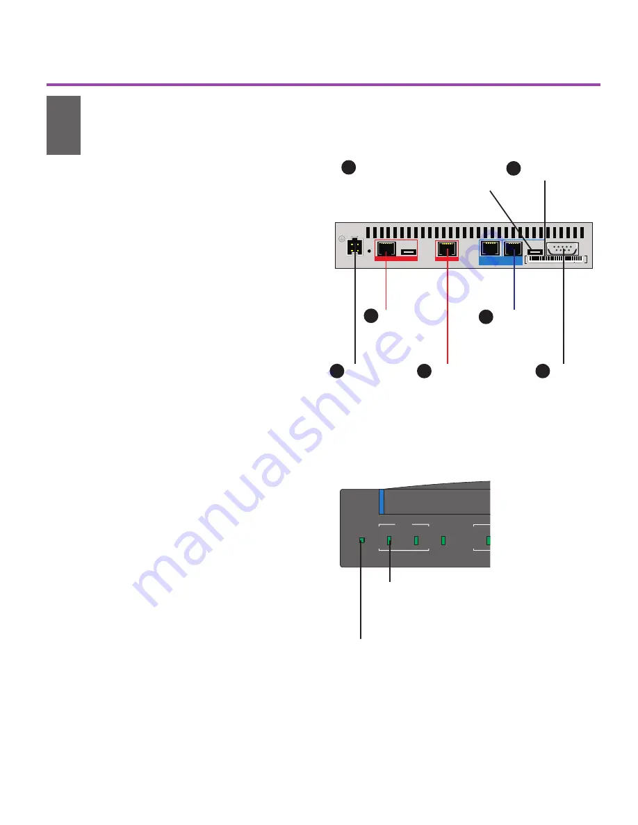
Figure 1. Connecting the Express 9545 Router. See
the user guide for details on connecting the LAN2 port.

Connect
to power
source

Connect
to LAN

Connect
to dial-up
modem
(optional)

3c

2a

4

Set switch:
Hub II   for hub or switch
PC X     for single computer

Write down
MAC address

2b

red

Connect to
HDSL2 line

3a

red

Connect
to ISDN
or IDSL

3b

1

Status LED

Green blinking - router is in factory default and ready
for configuration.

Red - error, router is not operational.

LAN LED

Green - port is operational and ready for
configuration.

Orange - port is down. Check cables.

Figure 2. Check Status and LAN LEDs. See page 10 of
this guide for a complete description of LEDs.

9545 Router Quick Start.p65

5/18/00, 8:53 AM

2

Содержание Express 9545

Страница 1: ...Start Express 9545 Router...

Страница 2: ...n assumes no responsibility for errors or omissions in this manual Nor does Intel make any commitment to update the information contained herein Other product and corporate names may be trademarks of...

Страница 3: ...tall Intel Device View 3 Install the Router in Intel Device View 4 Configure the Router 5 2 1 3 4 Configuration Worksheets 6 LED Indicators 10 Local Management 12 Viewing Online Manuals 13 Regulatory...

Страница 4: ...y do not change the 100W Norm switch setting Norm is the default setting and works for most installations See the user guide for details about this switch 3c If you are using the Console port for a di...

Страница 5: ...a PC running Microsoft Windows or through a Web browser We recommend using Intel Device View however the Local Management section in this guide describes alternate management methods 1 Insert the Inte...

Страница 6: ...elow 4 Assign the router s IP address see Figure 7 then follow the Device Install Wizard screen instructions The router s default IP address is 192 0 2 1 We recommend that you do not use the default a...

Страница 7: ...Intel Device View 3 Set up the port to which you want to add a connection Double click the port icon or select the port and click Set Up Port see Figure 8 Follow the screen instructions 4 Add remote c...

Страница 8: ...__ TEI Terminal Endpoint Identifier ________________ Get information from your telephone company for your type of connection These pages help you gather needed information before using a Connection Se...

Страница 9: ...ections only Packet Size m 128 m 256 m 512 m 1024 Window Size between 1 and 7 ______ m Only use PVCs Permanent Virtual Circuits m Use PVCs and SVCs Switched Virtual Circuits Lowest two way channel ___...

Страница 10: ...outer at the other end Remote user ID _____________________ Remote user password ___________________ Authentication for access to the remote site router from this router Your user ID _________________...

Страница 11: ...ed by the ISP each time the router makes a connection m Single IP address ___________________ m Multiple IP addresses If you are using multiple IP addresses choose one m Use your LAN IP address direct...

Страница 12: ...ons on the port 100 Mbps Green steady Ethernet LAN is operating at 100 Mbps Off Ethernet LAN is operating at 10 Mbps ISDN Network Green steady Connection to ISDN switch is established Orange steady No...

Страница 13: ...e steady Attempting to establish connection to the HDSL2 CSU on the data network switch Corresponds to a HDSL2 CSU Yellow Alarm Orange blinking Testing the line Red steady Error unable to transmit dat...

Страница 14: ...gement Remotely using Telnet Telnet to the IP address of the router from a terminal on the LAN or over a WAN connection to the router The router s default IP address is 192 0 2 1 with a subnet mask of...

Страница 15: ...screen click Install Add ons 3 Select Acrobat Reader 4 05 and click Ok Follow the on screen instructions to complete the installation Table 3 Online manuals available on the Intel Device View CD ROM M...

Страница 16: ...a is likely to cause harmful interference in which case the user will be required to correct the interference at his own expense FCC part 68 notice This equipment complies with Part 68 of the FCC rule...

Страница 17: ...f the local telecommunications company The equipment must also be installed using an acceptable method of connection The customer should be aware that compliance with the above conditions may not prev...

Страница 18: ...16...

Отзывы: