Board Identification Number
This product uses Plug and Play technology, including
hardware auto-configuration for IRQ and memory
address. This technology enables quick installation
and operation using the factory default hardware
settings.
The system software assigns board instance numbers
in ascending order (beginning with 0) as it detects
each board in your system. A board instance number is
the identification (ID) number used by the system
software to recognize the board. Each Board ID is
based on the SW100 rotary switch setting. See the
Physical Description
section.
NOTE:
The Board IDs automatically assigned by the
system may not correspond to a physical order in the
chassis.
Geographical Sequence
Leave SW100 set to Board ID 0 (default) to let the
system automatically assign board instance numbers
by PCI bus logical slot number. This method is not
available for ISA bus boards.
NOTE:
If you add or remove a board, the system may
change the existing board instance (ID) numbers.
Programmable Sequence
If you change the Board ID from the factory default of 0
to any other
unique
number, the software will use that
setting to identify the board.
Use a non-metallic screwdriver to turn SW100 to 1 of
16 board settings, 0–9 or A–F. You should assign
sequential numbers to each Intel® Dialogic® board,
starting at 1. This method is also used for all ISA bus
boards.
NOTE:
You should use the programmable Board ID
method in a Linux environment.
Precedence in Mixed Systems
In systems where both ISA and PCI boards exist, PCI
boards take precedence and are numbered before ISA
boards. Also, when using both geographical and
programmable assignment methods, PCI boards that
use Board ID setting 0 are numbered before PCI
boards that use settings 1–9 or A–F.
NOTES:
After the hardware and the system software
are installed in a Windows system, refer to the Intel®
Dialogic® Configuration Manager (DCM) utility to
retrieve the assigned board instance (ID) number(s).
After the hardware and the system software are
installed in a Linux system, refer to the proper
configuration files to retrieve the assigned board
instance (ID) number(s).
CT Bus Termination
C_2 and C_4* are terminated on boards located at
physical ends of bus using pins 1 and 2 of the P700
termination jumpers. This is only required for
MVIP(90).
Both CT_C8_(A&B) and CT_FRAME_(A&B) are
terminated on boards located at physical ends of bus
using pins 3 and 4 of the P700 termination jumpers.
Shunt Terminates
P700, Pins 1 and 2
C_2 and C_4*
P700, Pins 3 and 4
CT_FRAME_(A&B)
CT_C8_(A&B)
NOTE:
Only the boards at each end of the CT Bus
cable must have their termination jumper clips
installed.
Remote Loopback Switches (SW500, SW600)
The default settings (loopback disabled) for SW500
and SW600 are depicted in the
Physical Description
section. Once the firmware is downloaded, enable
loopback mode to verify the network connection. This
switch position overrides any board modes set by your
application.
Installing the Hardware
NOTE:
If you are adding additional Intel® hardware to
a system, you do not need to uninstall existing system
software.
1. With your computer on the static-safe work area,
switch off the power and disconnect all power
cords from the electrical outlets.
2. Remove the chassis cover.
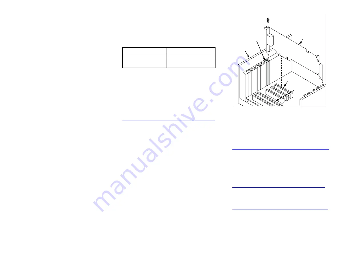
3. Select an empty PCI expansion bus slot and
remove the slot’s retaining screw and access
cover plate.
4. If you are not installing your board in an ISA
form factor PCI slot, remove the ISA edge
retainer bracket from the board.
5. Insert the edge connector of the board into the
bus slot. Press firmly until the board is securely
seated.
Installing the PCI Board
ISA Slot
PCI Slot
PCI
Board
Computer
Chassis
Remove
Cover
Plate
6. Replace and tighten the retaining screw to
secure the board firmly in the chassis slot.
7. Use the CT Bus cable to connect the board(s)
you are installing to other boards in the system.
8. Replace the computer cover when finished and
reconnect the power cords.
9. Turn the power to the chassis
ON
.
After Installing the Hardware
After installing the hardware, proceed with the system
software installation as described in the system
software documentation (if applicable).
For technical specifications and product information,
see the Intel® website at
http://www.intel.com/design/network/products/telecom
Direct Return Authorization (DRA) Process
To return a board for repair or credit in the American
geographies, use the online form at
http://www.intel.com/support/motherboards/draform.htm
To return a board for repair or credit in all other
geographies, please contact your distributor.


