Case Temperature Reference Metrology
R
Thermal/Mechanical Design Guide
77
D.4
Thermal Calibration and Controls
It is recommended that full and routine calibration of temperature measurement equipment be
performed before attempting to perform temperature case measurement of processors. Intel
recommends checking the meter probe set against known standards. This should be done at 0 ºC
(using ice bath or other stable temperature source) and at an elevated temperature, around 80 ºC
(using an appropriate temperature source).
Wire gauge and length also should be considered as some less expensive measurement systems
are heavily impacted by impedance. There are numerous resources available throughout the
industry to assist with implementation of proper controls for thermal measurements.
Note:
1.
It is recommended to follow standard safety procedures and wear safety items like glasses for
cutting the IHS and gloves for chemical handling.
2.
Ask your Intel field sales representative if you would like assistance to groove and/or install a
thermocouple according to the reference process.
D.5 IHS
Groove
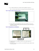
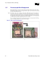
Cut a groove in the package IHS according to the drawing given in Figure 27.
.
Содержание 640 - Pentium 4 640 3.2GHz 800MHz 2MB Socket 775 CPU
Страница 14: ...Introduction R 14 Thermal Mechanical Design Guide ...
Страница 38: ...Thermal Management Logic and Thermal Monitor Feature R 38 Thermal Mechanical Design Guide ...
Страница 52: ...Intel Thermal Mechanical Reference Design Information R 52 Thermal Mechanical Design Guide ...
Страница 60: ...Acoustic Fan Speed Control R 60 Thermal Mechanical Design Guide ...
Страница 72: ...Heatsink Clip Load Metrology R 72 Thermal Mechanical Design Guide ...
Страница 97: ...Mechanical Drawings R Thermal Mechanical Design Guide 97 Figure 48 Reference Clip Drawings Sheet 1 ...
Страница 98: ...Mechanical Drawings R 98 Thermal Mechanical Design Guide Figure 49 Reference Clip Drawings Sheet 2 ...
Страница 99: ...Mechanical Drawings R Thermal Mechanical Design Guide 99 Figure 50 Reference Fastener Sheet 1 ...
Страница 100: ...Mechanical Drawings R 100 Thermal Mechanical Design Guide Figure 51 Reference Fastener Sheet 2 ...
Страница 101: ...Mechanical Drawings R Thermal Mechanical Design Guide 101 Figure 52 Reference Fastener Sheet 3 ...
Страница 102: ...Mechanical Drawings R 102 Thermal Mechanical Design Guide Figure 53 Reference Fastener Sheet 4 ...
Страница 103: ...Mechanical Drawings R Thermal Mechanical Design Guide 103 Figure 54 Clip Heatsink Assembly ...
Страница 104: ...Mechanical Drawings R 104 Thermal Mechanical Design Guide Figure 55 Intel R RCBFH 3 Reference Solution Assembly ...


