


LGA775 Socket Heatsink Loading
R
62
Thermal/Mechanical Design Guide
Simulation shows that the solder joint force (F
axial
) is proportional to the board deflection
measured along the socket diagonal. The matching of F
axial
required to protect the LGA775
socket solder joint in temperature cycling is equivalent to matching a target MB deflection.
Therefore, the heatsink preload for LGA775 socket solder joint protection against fatigue failure
can be more generally defined as the load required to create a target board downward deflection
throughout the life of the product.
This board deflection metric provides guidance for mechanical designs that differ from the
reference design for ATX//µATX form factor.
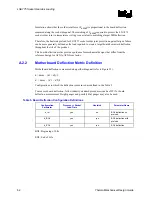
A.2.2
Motherboard Deflection Metric Definition
Motherboard deflection is measured along either diagonal (refer to Figure 22):
d = dmax – (d1 + d2)/2
d’ = dmax – (d’1 + d’2)/2
Configurations in which the deflection is measured are defined in the Table 5.
To measure board deflection, follow industry standard procedures (such as IPC) for board
deflection measurement. Height gauges and possibly dial gauges may also be used.
Table 5. Board Deflection Configuration Definitions
Configuration
Parameter
Pro Socket
Load Plate
Heatsink Parameter
Name
d_ref
yes
no
BOL deflection, no
preload
d_BOL
yes
yes
BOL deflection with
preload
d_EOL yes yes
EOL
deflection
BOL: Beginning of Life
EOL: End of Life
Содержание 640 - Pentium 4 640 3.2GHz 800MHz 2MB Socket 775 CPU
Страница 14: ...Introduction R 14 Thermal Mechanical Design Guide ...
Страница 38: ...Thermal Management Logic and Thermal Monitor Feature R 38 Thermal Mechanical Design Guide ...
Страница 52: ...Intel Thermal Mechanical Reference Design Information R 52 Thermal Mechanical Design Guide ...
Страница 60: ...Acoustic Fan Speed Control R 60 Thermal Mechanical Design Guide ...
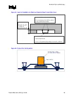
Страница 72: ...Heatsink Clip Load Metrology R 72 Thermal Mechanical Design Guide ...
Страница 97: ...Mechanical Drawings R Thermal Mechanical Design Guide 97 Figure 48 Reference Clip Drawings Sheet 1 ...
Страница 98: ...Mechanical Drawings R 98 Thermal Mechanical Design Guide Figure 49 Reference Clip Drawings Sheet 2 ...
Страница 99: ...Mechanical Drawings R Thermal Mechanical Design Guide 99 Figure 50 Reference Fastener Sheet 1 ...
Страница 100: ...Mechanical Drawings R 100 Thermal Mechanical Design Guide Figure 51 Reference Fastener Sheet 2 ...
Страница 101: ...Mechanical Drawings R Thermal Mechanical Design Guide 101 Figure 52 Reference Fastener Sheet 3 ...
Страница 102: ...Mechanical Drawings R 102 Thermal Mechanical Design Guide Figure 53 Reference Fastener Sheet 4 ...
Страница 103: ...Mechanical Drawings R Thermal Mechanical Design Guide 103 Figure 54 Clip Heatsink Assembly ...
Страница 104: ...Mechanical Drawings R 104 Thermal Mechanical Design Guide Figure 55 Intel R RCBFH 3 Reference Solution Assembly ...


