Thermal Management
76
Datasheet, Volume 1
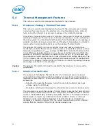
mode, the duty cycle can be programmed in either 12.5% or 6.25% increments
(discoverable using CPU ID). Thermal throttling using this method will modulate each
processor core’s clock independently.
5.4.2.1.2
I/O Emulation-Based On-Demand Mode
I/O emulation-based clock modulation provides legacy support for operating system
software that initiates clock modulation through I/O writes to ACPI defined processor
clock control registers on the chipset (PROC_CNT). Thermal throttling using this
method will modulate all processor cores simultaneously.
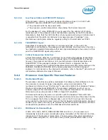
5.4.3
Memory Controller Specific Thermal Features
The memory controller provides the ability to initiate memory throttling based upon
memory temperature. The memory temperature can be provided to the memory
controller using PECI or can be estimated by the memory controller based upon
memory activity. The temperature trigger points are programmable by memory
mapped IO registers.
5.4.3.1
Programmable Trip Points
This memory controller provides programmable critical, hot and warm trip points.
Crossing a critical trip point forces a system shutdown. Crossing a hot or warm trip
point will initiate throttling. The amount of memory throttle at each trip point is
programmable.
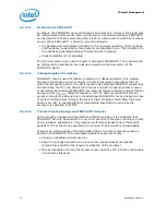
5.4.4
Platform Environment Control Interface (PECI)
The Platform Environment Control Interface (PECI) is a one-wire interface that provides
a communication channel between Intel processor and chipset components to external
monitoring devices. The processor implements a PECI interface to allow communication
of processor thermal information to other devices on the platform. The processor
provides a digital thermal sensor (DTS) for fan speed control. The DTS is calibrated at
the factory to provide a digital representation of relative processor temperature.
Averaged DTS values are read using the PECI interface.
The PECI physical layer is a self-clocked one-wire bus that begins each bit with a
driven, rising edge from an idle level near zero volts. The duration of the signal driven
high depends on whether the bit value is a Logic 0 or Logic 1. PECI also includes
variable data transfer rate established with every message. The single wire interface
provides low board routing overhead for the multiple load connections in the congested
routing area near the processor and chipset components. Bus speed, error checking,
and low protocol overhead provides adequate link bandwidth and reliability to transfer
critical device operating conditions and configuration information.
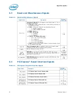
5.4.4.1
Fan Speed Control with Digital Thermal Sensor
Digital Thermal Sensor based fan speed control (T
FAN
) is a recommended feature to
achieve optimal thermal performance. At the T
FAN
temperature, Intel recommends full
cooling capability well before the DTS reading reaches T
j,max
. An example of this would
be T
FAN
= T
j,max
– 10 ºC.
§ §
Содержание 2ND GENERATION CORE PROCESSOR FAMILY DESKTOP - VOLUME 1 01-2011
Страница 10: ...10 Datasheet Volume 1 Revision History Revision Number Description Date 001 Initial Release January 2011 ...
Страница 22: ...Introduction 22 Datasheet Volume 1 ...
Страница 62: ...Power Management 62 Datasheet Volume 1 ...
Страница 86: ...Signal Description 86 Datasheet Volume 1 ...
Страница 106: ...Electrical Specifications 106 Datasheet Volume 1 ...
Страница 172: ...DDR Data Swizzling 172 Datasheet Volume 1 ...


