InSinkErator Instant Warm Handwash System Скачать руководство пользователя страница 9

9

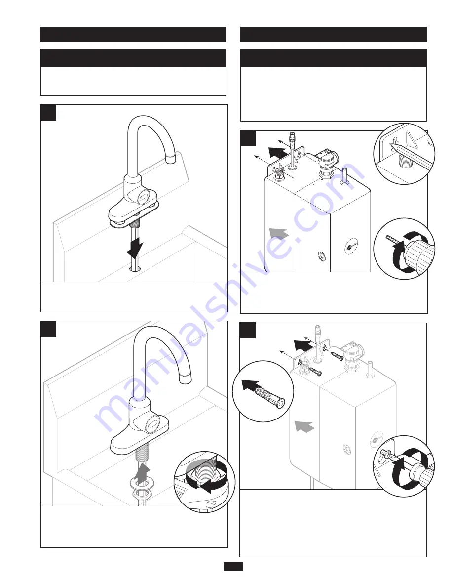
4. MOUNTING THE TANK

PROPERTY DAMAGE

Tank must be located within 16" (41 cm) of faucet 

and 84" (213 cm) or less of a GFCI outlet, to 

accommodate the supplied 7' cord. DO NOT 

extend plumbing or electrical lines.

NOTICE

3. INSTALLING THE FAUCET

PROPERTY DAMAGE

Do not pinch wires or tubing. 

NOTICE

4

Feed hose, sensor wire and threaded sleeve(s) 

into hole until faucet rests on deck/splash.

1

5

2

From underneath or behind sink, install washer(s)  

and large nut(s) onto threaded sleeve(s). Use an 

adjustable wrench to secure.

2

2

7

3

1

Screws provided are for use in wood studs or 

cabinets only. Use wall anchors for installation 

into drywall. Turn screws into pre-drilled holes, 

leaving 1/4" (6 mm) exposed. Hang the tank 

on the screws. Tighten the screws with only 

1/2 turn clockwise.

A

B

1

1

6

3

2

From underneath the sink, place tank against 

the wall and mark hole locations. Pre-drill 

1/8" (3 mm) pilot holes at marks.

C

D

Содержание Instant Warm Handwash System

Страница 1: ...tallation Care Use Manual www insinkerator com foodservice Please be certain that the person who installs or uses this appliance carefully reads and understands the Safety Instructions contained in th...

Страница 2: ...when temperatures are expected to drop below 40 F 4 C see Seasonal Storage Drainage section Do not use a torch or other high temperature sources near system plastic fittings or plastic plumbing Do not...

Страница 3: ...e replaced in order to avoid a hazard Do not connect to water supply exceeding 80 F 27 C Do not connect to the water supply if the water pressure exceeds 70 PSI IMPORTANT SAFETY INFORMATION WARNING in...

Страница 4: ...of owner and or installer Reference the latest version of the Uniform Plumbing Code UPC for specific details and requirements IMPORTANT SAFETY INFORMATION NOTICE The maximum working pressure of 150 PS...

Страница 5: ...standard dedicated 115 volt GFCI outlet DO NOT extend plumbing or electrical lines Figure 1 Typical Installation Shown Components In This Package Ensure the incoming water line is connected shutoff va...

Страница 6: ...es 2 Screw Driver M2 5 Hex Key Discharge Pipe Water Supply Hose Tape Measure Level Basin Nut Wrench Thermometer Shutoff Valve Anchors SUPPLIES YOU MAY NEED SUPPLIES NEEDED Required Tools Materials Sin...

Страница 7: ...mm These instructions are separated into main sections indicated by numbers and subsections indicated by capital letters The manual is setup this way to allow you to take a break at any point after co...

Страница 8: ...ll spout into faucet base and tighten set screw to secure 2 1 1 1 1 3 2 Install threaded sleeve s into bottom of faucet A 2 2 2 After inserting sensor connection wire install sensor into faucet base T...

Страница 9: ...l faucet rests on deck splash 1 5 2 From underneath or behind sink install washer s and large nut s onto threaded sleeve s Use an adjustable wrench to secure 2 2 7 3 1 Screws provided are for use in w...

Страница 10: ...hose 2 9 Insert tubing into fitting from the faucet hose and press until it bottoms out Pull on connections to insure tubes are fully seated Tube should insert approximately 5 8 10 Connect sensor fro...

Страница 11: ...xceeding 80 F 27 C PROPERTY DAMAGE Join remaining tube to cold water supply only NOTICE 12 Make sure the water hose is properly connected to the cold water source with valve 8 FINAL INSTALLATION 13 Tu...

Страница 12: ...o prevent accidental or unauthorized temperature adjustment Wait a few minutes for tank to re heat and re check temperature 2 If needed turn temperature adjustment screw counterclockwise for hotter or...

Страница 13: ...d place a hand in the desired sensor activation location Wait for 5 seconds until the red LED on the sensor turns off Test the new activation location by placing a hand in front of the sensor d the ca...

Страница 14: ...pside down and drain water into the sink PERSONAL INJURY n Regularly check for signs of corrosion by examining the appearance of the dispensed water n If there is any discoloration or rusty appearance...

Страница 15: ...h TMV is not adjusted to your needs Adjust TMV and re measure output water temperature as described in the Adjusting the Thermostat section on page 12 of this manual Undesired output stream Debris in...

Страница 16: ...d warranty Only an authorized InSinkErator service representative may provide warranty service InSinkErator is not responsible for warranty claims arising from work performed on your InSinkErator Prod...

Отзывы: