background image

A

V I

N

4

7

HDMI 3

ANT/

CABLE IN

DIGITAL

OUTPUT

USB

HDMI 1

(DVI)

(COAXIAL)

 VIDEO

AUDIO

L

R

COMPON ENT

 IN

P

B

 P

R

Y

1

2

3

AV IN

5

6

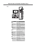
Connect  a  computer  to  these  jacks.  For 
more  information,  see  “Connecting  a 
computer” section. 
Connect  headphones  to  this  jack.  For 
more  information,  see  “Connecting 
headphones” section. 
OR
Connect an audio amplifier to this jack.

Back 

# Item 

Description 

1

USB

HDMI3

Headphone/AUDIO OUT

Connect a USB flash drive to this jack. For 
more information, see “Connecting a USB 
flash drive” section. 

Connect  an  HDMI  device  to  this  jack.  An 
HDMI cable carries both video and sound. 
You  do  not  need  to  make  an  audio 
connection for an HDMI device. 

Connect an antenna, cable TV, or satellite 
TV box to this jack. For more information, 
see  “Connecting  an  antenna  or  cable  TV 
(no box)” section. 

Connect a composite video device, such as 
a VCR, to these jacks. 

Connect  a  component  video  device  to 
these  jacks.  For  more  information,  see 
“Using component video (better)” section.  

PC IN VGA/AUDIO

ANT/CABLE IN 

AV IN 

COMPONENT IN 

2

3

4

5

8

9

Connect  a  digital  audio  amplifier  to  this 
jack  to  listen  to  TV  audio  through  the 
amplifier  speakers.  For  more  information, 
see  “Connecting  a  basic  home  theater 
system” section. 

DIGITAL OUTPUT
(COAXIAL)

HDMI1 (DVI)

Connect an HDMI device to this jack. 

10

HDMI 2

(ARC)

PC IN

VGA

PC/DVI AUDIO

/AUDIO OUT

8

9

10

HDMI2 (with ARC)

6

7

Connect an HDMI device to this jack. 

Main Unit (Front View/Side View/Rear View)

Содержание NS-46L240A13

Страница 1: ...Part 9246MF7010 Model Line ProductYear CONTENTS Product Safety Servicing Guidelines 2 Remote Control Unit 3 Main Unit Front View Side View Rear View 4 Specifications 6 Alignment Instructions 7 Block Diagram 15 Troubleshooting Guides 16 Exploded View Parts List 19 Wiring Diagram 20 Appendix Schematic Diagram Printed Circuit Board Layouts ...

Страница 2: ...on doesn t represent failure This ghost shadow may remain in the picture for a period of time several minutes But when operating it please avoid displaying still picture in high brightness for a long time Points for attention during installation 1 The front panel of LCD screen is of glass When installing it please make sure to put it in place 2 For service or installation it s necessary to use spe...

Страница 3: ...ease or decrease the volume Press to set the sleep timer For more information see Setting the sleep timer section Press to select the aspect ratio For more information see Adjusting the TV picture section Press to select the TV as the video input source This button has no function in this model Press to go to the last viewed channel Press to close the on screen menu Press to display the channel ba...

Страница 4: ...rough it To completely disconnect power unplug the power cord Press to go to the next or previous channel in the channel list CH v Item Description 1 2 Power indicator Receives signals from the remote control Do not block Remote sensor Lights red when your TV is in standby mode For more information see Turning your TV on or off section 5 6 7 Front side control panel 32 46 model 1 2 CH VOL VOL MENU...

Страница 5: ...e an audio connection for an HDMI device Connect an antenna cable TV or satellite TV box to this jack For more information see Connecting an antenna or cable TV no box section Connect a composite video device such as a VCR to these jacks Connect a component video device to these jacks For more information see Using component video better section PC IN VGA AUDIO ANT CABLE IN AV IN COMPONENT IN 2 3 ...

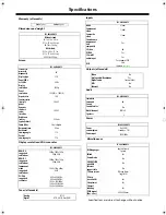
Страница 6: ...er NS 46L240A13 HDMI 3 side Component video 1 side Composite video 1 side Shared audio component and composite Yes S Video No PC VGA Yes 3 5mm PC audio input Yes USB Yes supports JPEG and firmware upgrade Video No Analog audio Headphone Yes Digital audio 1 coaxial side WiFi No Ethernet No NS 46L240A13 Simulated Surround Sound No Sound Leveler Watts channel 10W 2 Speakers NS 46L240A13 Power consump...

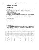
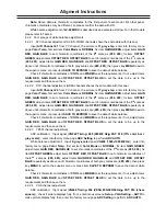
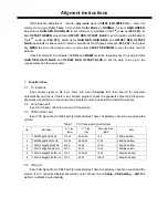
Страница 7: ...HDMI signal generator CA 210 3 Adjustment Processes 3 1 Power voltage test According to the wiring diagram 92XXMF7001JL or 92XXMF7501JL connect power board assembly data processing assembly IR Key board assembly backlight board assembly correctly supply with power press button standby to power on the TV set 3 1 1 Model LC 37 39 42 46MFXX a Test voltage of X504 each pin on power board in turn shown...

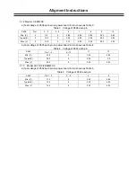
Страница 8: ...5 35 3 30 5 35 b Test voltage of X503 each pin on power board in turn shown as Table 4 Table 4 Voltage of X503 each pin X503 Pin 1 5 6 10 11 12 Min V 23 8 0 3 25 4 85 Typical V 24 0 0 3 30 5 0 Max V 25 2 0 3 30 5 35 3 1 3 Model LE 15 19 22 24MFXX a Test voltage of X502 each pin on power board in turn shown as Table 5 Table 5 Voltage of X502 each pin X502 Pin 1 2 3 4 5 6 Min V 11 3 0 3 25 4 85 Typi...

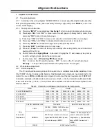
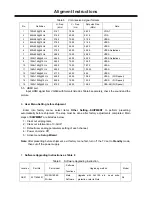
Страница 9: ...ck TV function omitted channel analog parameters control etc check earphone speakers output Input HDMI signal mode check YPbPr functions Input VGA signal check display and all functions such as analog parameter H V center etc Default settings before shipment Check accessory and packing Input AV SVIDEO signal check relevant functions Input HDMI signal check display and all functions such as analog ...

Страница 10: ...ff state when power on the TV set again 4 2 White balance adjustment 4 2 1 Before adjustment The TV set should be working above 30 minutes to be in a stabler state before adjustment Use CA 210 BBY channel to adjust white balance Only Normal color temperature need adjusting for the model To ensure COOL and Warm color temperature also meet the test requirements of BESTBUY chromatic coordinates of br...

Страница 11: ...chromatic coordinates of the 3rd scale as 285 293 adjust items GAIN RED GAIN BLUE and OFFSET RED OFFSET BLUE repeatedly as above until chromatic coordinates of both gray scales are 285 293 then press key MENU to exit to the superior menu or press item SAVE TO EEPROM to save the data of white balance Check if chromatic coordinates of COOL and WARM meet the requirements if not adjust items GAIN RED ...

Страница 12: ...rst then search for programs automatically and check if there is any omitted program check the speakers output and the picture especially pay attention to check searched programs must include NTSC and ATSC signals 5 2 AV S Video port Input AV S signal check the sound and the picture 5 3 YPbPr YCbCr port Input YUV signal from VG848 with formats listed as Table 7 separately check the sound and the p...

Страница 13: ...nel 5 5 HDMI port Input HDMI signal from VG849 with formats listed as Table 8 separately check the sound and the picture 6 User Menu Setting before shipment Enter into factory menu select items Other Setting SHIPMENT to perform presetting automatically before shipment The step must be done after factory adjustments completed Main steps of SHIPMENT are listed as below 1 Clear out all programs 2 Cle...

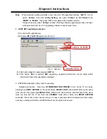
Страница 14: ... 4 Click button Run to perform KEY upgrading upgrading information will be listed within information frame after upgrading completed 9 EEPROM initialization Only used if necessary Detailed procedures Press key IR POWER KEYPAD POWER to turn on the TV set keep pressing key INPUT SOURCE on the panel before SHOW LOGO until indicator light on the panel turns into red then press keys MENU VOL CH in turn...

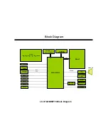
Страница 15: ...32M16DG_AC POWER 12V 5V 3 3V 1 8V 1 2V STB5 0V DIF LC 37 42 46MF70 Block Diagram TUNUER ENV56U04D8F VIDEO HDMI 1 HDMI 2 HDMI 3 YPbPr AUDIO OUT HEADPHONE RS232 COAXIAL SERVICE PORT JPEG HP AMP BH3547F LVDS IIC VIDEO YPbPr AUDIO VGA AUDIO SPEAKER IIC IIS Block Diagram ...

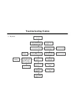
Страница 16: ...OWER on remote control or key board to turn on the TV set check if indicator light is twinkling Check power board assembly Check if the voltage of X604 PIN6 on main board is high level Check if the voltage of X604 PIN10 on main board is high level N Y 1 No sound no picture N N Y Y Y Check N610 and its peripheral circuits N Check 24V on power board N Y Check power board assembly N Troubleshooting G...

Страница 17: ...channel has no picture Check DIF output from TUNER0 PIN13 14 Check TUNER0 and its peripheral circuits Replace main board Check if pressing keys on remote control or key board can operate the TV set N Y Check if there is backlight Y Y N Y Replace main board Y Replace main board N OTHER TV N N Check power board N N Check if the voltage of X604 PIN10 on main board is high level Y Check backlight of d...

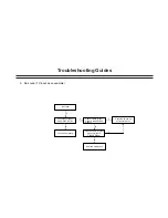
Страница 18: ...eck power board Check if there is input signal to NV02 PIN4 PIN12 Check if there is output signal from N612 PIN63 PIN64 Replace main board Check NV02 and its peripheral circuits Y Y N N N Y Y 3 No sound TV input as an example Troubleshooting Guides ...

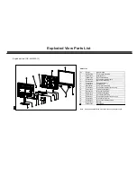
Страница 19: ...ssembly 9 58A0097200 Wall mounting bracket down left 10 581AF72200 Interface baffle down 11 6MF0050110 Main board assembly 12 5810E75010 Interface baffle right 13 6153375000 Panel holder assembly 14 58A0097100 Wall mounting bracket down right 15 58A0100400 Main board connecter 16 58A008420A Wall mounting bracket right 17 6170935000 Speaker 18 635MS00603 IR assembly Note Design and specification ar...

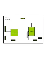
Страница 20: ...Panel MAIN BOARD POWER BOARD IR BOARD KEY BOARD SPEAKER SPEAKER LVDS SOCKET BACKLIGHT SOCKET Wiring Diagram ...

Страница 21: ...ducción ñ Gu a de Seguridad de Productos de Mantenimiento 2 Unidad de control remoto 3 Elementos principales Vista frontal Vista lateral Vista posterior 4 Especificaciones 6 Instruciones de Alineación 7 Diagrama de bloques 15 Guías de la solución de problemas 16 Lista del imagen de la descomposición de piezas 19 Diagrama de cableado 20 í Ap ndice Diagrama esquem tico composiciòn impresa de làmina ...

Страница 22: ...o enchufar el cable de conexión 8 Cuando operar o instalar LCD por favor no sujetos los componentes de cristal líquido para doblar torcer o extrusión para que no choque accidente por si acaso 9 Como la mayoría de los circuitos en la pantalla LCD TV se compone de circuitos integrados CMOS es necesario prestar atención a la lucha contra la estática Antes de dar servicio de TV LCD asegúrese de tomar ...

Страница 23: ...umen 13 SLEEP Pulse para ajustar el temporizador de apagado automático Para más información consulte la sección Configuración del temporizador de apagado automático sección 14 ZOOM Pulse para seleccionar la relación de aspecto Para más información consulte Ajuste de la imagen de TV sección 15 TV Pulse para seleccionar la TV como fuente de entrada de vídeo 16 ACC Este botón no tiene ninguna función...

Страница 24: ...lte Encendido del televisor encendido o apagado sección 3 MENÚ Pulse para abrir el menú en pantalla 4 ENTRADA Pulse para seleccionar la fuente de entrada de video 5 VOL Pulse para aumentar y disminuir el volumen 6 CH V Pulse para ir al canal anterior o siguiente en la lista de canales 7 ENETGÍA Pulse para encender su TV Pulse otra vez para poner su TV en el modo de espera Cuando su TV está en el m...

Страница 25: ...nformación consulte Conexión de un sistema de cine en casa básico sección HDMI3 Conecte un dispositivo de HDMI a este gato Un cable de HDMI lleva video y sonido Usted no se necesita hacer una conexión de audio a un dispositivo de HDMI HDMI2 con ARC Conecte un dispositivo de HDMI a este gato HDMI1 DVI Conecte un dispositivo de HDMI a este gato ANT CABLE IN Conecte una antena TV por cable o caja de ...

Страница 26: ...0i PC VGA Tasas de exploración sugerida 640 480 60Hz 800 600 60Hz 1024 768 60Hz 1280 1024 60Hz 1920 1080 60Hz Sintonizador todos los modelos Analógico NTSC Digital ATSC 8 VSB Clear QAM Entradas NS 46L240A13 HDMI 3 lateral Video por componentes 1 lateral Video compuesto 1 lateral Audio compartido por componentes y compuesto Sí S Video No PC VGA Sí Entrada de audio de PC 3 5mm Sí Puerto de servicio ...

Страница 27: ...ador de señal CA 210 3 Ajuste de los Procesos 3 1 Prueba de voltaje Según el diagrama del cableado 92XXMF7001JL o 92XXMF7501JL se puede conectar el montaje de la tarjeta de potencia el montaje de procesos de datos el montaje de la tarjeta de IR Key el montaje de la tarjeta de retroiluminación correctamente cuando conecta la energía pulse el botón de espera para encender el televisor 3 1 1 Modelo L...

Страница 28: ...3 15 5 35 5 35 3 30 5 35 b Voltaje de prueba de X503 cada pin de tarjeta de potencia a su vez se muestra como la Tabla 4 En la tabla 4 voltaje de cada pin X503 X503 Pin 1 5 6 10 11 12 Min V 23 8 0 3 25 4 85 Typical V 24 0 0 3 30 5 0 Max V 25 2 0 3 30 5 35 3 1 3 Modelo LE 15 19 22 24MFXX a Voltaje de prueba de X502 cada pin de tarjeta de potencia a su vez se muestra como la Tabla 5 En la tabla 5 vo...

Страница 29: ...de altavoz Entre AV SVIDEO señal compruebe funciones relevantes Entre HDMI señal modo compruebe YPbPr funciones Entre VGA señal compruebe visualización y todas las funciones tal como paramétro analógico centro H V etc Entre HDMI señal compruebe visualización y todas las funciones tal como paramétro analógico centro H V etc Ajustes por defecto antes del cargo Compruebe los accesesorios y embalajes ...

Страница 30: ... televisor con un solo paso Off para encender el televisor con dos pasos Memory para mantenerse en el poder off estado último al encender el televisor otra vez 4 2 Ajuste de equilibrio blanco 4 2 1 Antes de ajuste El televisor debe estar trabajando por encima de 30 minutos para estar en un estado más estable antes de los ajustes Use CA 210 BBY canal para ajustar el equilibrio blanco sólo la temper...

Страница 31: ... BLUE para establecer las coordenadas cromáticas de la escala 3rd en 285 293 ajústelos de Ganancia de Rojo GAIN RED Ganancia de Azul GAIN BLUE y Offset Rojo OFFSET RED Offset Azul OFFSET BLUE repetidamente de arriba hasta las coordenadas cromáticas de ambas escalas de grises son 285 293 a continuación pulse la tecla Menú MENU para volver al menú superior o pulse el botón SAVE TO EEPROM para guarda...

Страница 32: ...T BLUE para fijar la fecha para cumplir con los requisitos y luego guardarlos 5 Comprobación de Función 5 1 Funciones de TV Entra la señal central a RF puerto primeramente entra en el menú de Canal Channel luego busque las programas en forma automática y comprueba si exisite algún programa omitido comprueba la salida de altavoz y la imagen sobre todo preste atención a comprobar los programas busca...

Страница 33: ...n los formatos listados como Tabla 8 separada compruebe el sonido y la imagen 6 Ajuste del Menú de Usuario antes de embarque Entra en el menu de fábrica seleccione ítem Other Setting SHIPMENT a realizar el preajuste de forma automática antes de embarque El paso se debe cumplir luego del ajuste de fábrica Los pasos principales de EMBARQUE se listan como los siguientes 1 Quite todos los programas 2 ...

Страница 34: ...umento de ISP 3 Click botón open para cargar KEY archivo encriptado 4 Click botón Run para realizar KEY mejora información de mejora se va a listar dentro del Marco de información después de que la mejora termine 9 EEPROM inicialización sólo usada si es necesario Los procedimientos detallados Pulse el botón IR POWER KEYPAD POWER para encender el televisor mantenga pulsado el botón INPUT SOURCE en ...

Страница 35: ...deo YPbPr HDMI 1 HDMI 2 HDMI 3 LC 37 42 46MF70 Diagrama de bloques DDR SDRAM NT5TU32M16DG_AC SPI Flash MX25L1606E Altavoz Puerto de servicio y JPEG AMP TAS5707 HP AMP BH3547F Salida de audio y auriculares Coaxial RS232 MSD3391DS II IIS IIC DIF Video YPbPr Audio Tunuer ENV56U04D8F ...

Страница 36: ...NERGÏA en el control remoto o el telcado para encender el televisor compruebe si la luz indicadora está brillando Compruebe si el voltaje de X604 PIN6 en la tarjeta de energía está en nivel alto Compruebe el montaje de la tarjeta de enegía Compruebe si el voltaje de X604 PIN10 en la tarjeta principal está en nivel alto Compruebe N610 y sus circuitos periféricos Compruebe 24V sobre la tarjeta de en...

Страница 37: ...ebe si hay retroiluminación Pulsa la tecla menu para comprobar si el menú de OSD muestra normal Todos los canales no tienen imagen Cuál canal no tiene imagen Compruebe la salida de DIF de TUNER0 PIN13 14 Compruebe TUNER0 y sus circuitos periféricos Reemplace la placa principal Compruebe si hay 24V en la tarjeta de potencia Compruebe si el voltaje de X604 PIN10 en la placa principal está en nivel a...

Страница 38: ...del TV como un ejemplo No sonido Compruebe el voltaje de X604 PIN2 PIN3 Compruebe la tarjeta de potencia Compruebe si hay señal de entrada a NV02 PIN4 PIN12 Compruebe si hay señal de salida desde N612 PIN63 PIN64 Reponga la tarjeta principal Compruebe NV02 y sus circuitos periféricos ...

Страница 39: ...olo de pie 8 6MF0052010 Conjunto del tablero de alimentación 9 58A0097200 Soporte de montaje en pared abajo izquierda 10 581AF72200 Deflector de interfaz abajo 11 6MF0050110 Conjunto de la placa principal 12 5810E75010 Deflector de interfaz derecha 13 6153375000 Conjunto de Panel titular 14 58A0097100 Soporte de montaje en pared abajo derecha 15 58A0100400 Conector de la placa principal 16 58A0084...

Страница 40: ...Diagrama de cableado Panel Tablero de alimentación Placa principal IR bordo Altavoz Altavoz LVDS Zócalo Retroiluminación zócala Teclado ...

Страница 41: ... RB12 10K XB05 UBA 100 W 1 2 3 4 G G 5V_EOP RB43 1K 3 3V_STANDBY RB28 5 1 HPOUT_L 003 D6 EOP_PWRON 003 A3 003 F3 RB39 10K RB14 12K VGA_LIN 003 C4 RB27 5 1 CB34 1u NB04 BH3547F 1 OUT1 2 MUTE 3 IN1 4 GND 5 IN2 6 BIAS 7 OUT2 8 VCC CB05 330p 5V_NORMAL CB33 1u RB26 0 HOST_1DP 003 D1 CB06 560p HPOUT_R 003 D6 RB13 10K CB07 560p CB28 1n RB42 0 5V_EOP VB03 2SA1576UB CB04 330p RB15 12K CB20 100n VGA_RIN 003...

Страница 42: ...VDD OUT 33 BST_D 34 PVDD_D_34 35 PVDD_D3_5 36 OUT_D 37 PGND_CD_37 38 PGND_CD_38 39 OUT_C 40 PVDD_C_40 41 PVDD_C_41 42 BST_C 43 BST_B 44 PVDD_B_44 45 PVDD_B_45 46 OUT_B 47 PGND_AB_47 48 PGND_AB_48 CV12 100n C V 0 3 1 0 0 n AMP_STB C V 1 1 1 0 u 1 0 V 3 3V_NORMAL CV18 1u SCLK RV21 470 12V_AUDIO C V 3 7 1 u RV13 10K RV23 100 DV01 LL4148 C V 2 3 3 3 0 p CV31 100n RV16 47 C V 2 8 3 3 0 p CV22 39n 12V_A...

Страница 43: ...2P 96 DDCDC_CK 97 LVA4N 98 LVA4P 99 LVA3N 100 LVA3P 21 RXA2N 22 RXA2P 46 CVBSOUT 47 AUL0 54 AVDD_AU25 55 AUL2 79 DDCR_DA 80 UARP_RX 23 DDCDA_CK 24 ARC0 25 VDDC25 48 AUR0 49 AUL1 50 AUR1 51 AUVRM 52 AUVRP 53 AUVAG 76 GPIO71 77 GND77 78 DDCR_CK 101 LVACKN 102 LVACKP 103 LVA2N 104 LVA2P 105 LVA1N 106 LVA1P 107 LVA0N 108 LVA0P 109 AVDD_LPLL 110 AVDD_MOD 111 AVDDL_MOD 112 LVB4N 113 LVB4P 114 LVB3N 115 ...

Страница 44: ...10K R569 47K R574 10K R572 10K R570 10K C544 100n C553 100n C552 10n C546 100n N505 N507 N506 C507 1u 450V C511 1u 450V C508 47n C527 4 7n C528 100n C531 22u 50V D504 CD4148WP D507 CD4148WP D509 CD4148WP D521 CD4148WP D523 CD4148WP D520 MMSZ5254B D522 MMSZ5245B C514 220p 1KV R523 2 2M R524 2 2M R505 1M R506 1M D508 MMSZ5245B C554 220u 25V C556 220u 25V L507 R512 10 D513 ES1J R519 NC R522 NC R526 N...

Страница 45: ......

Страница 46: ......

Страница 47: ......

Страница 48: ......

Отзывы: