Inovus Medical Lapar Pro Скачать руководство пользователя страница 6

P5.

17 

|

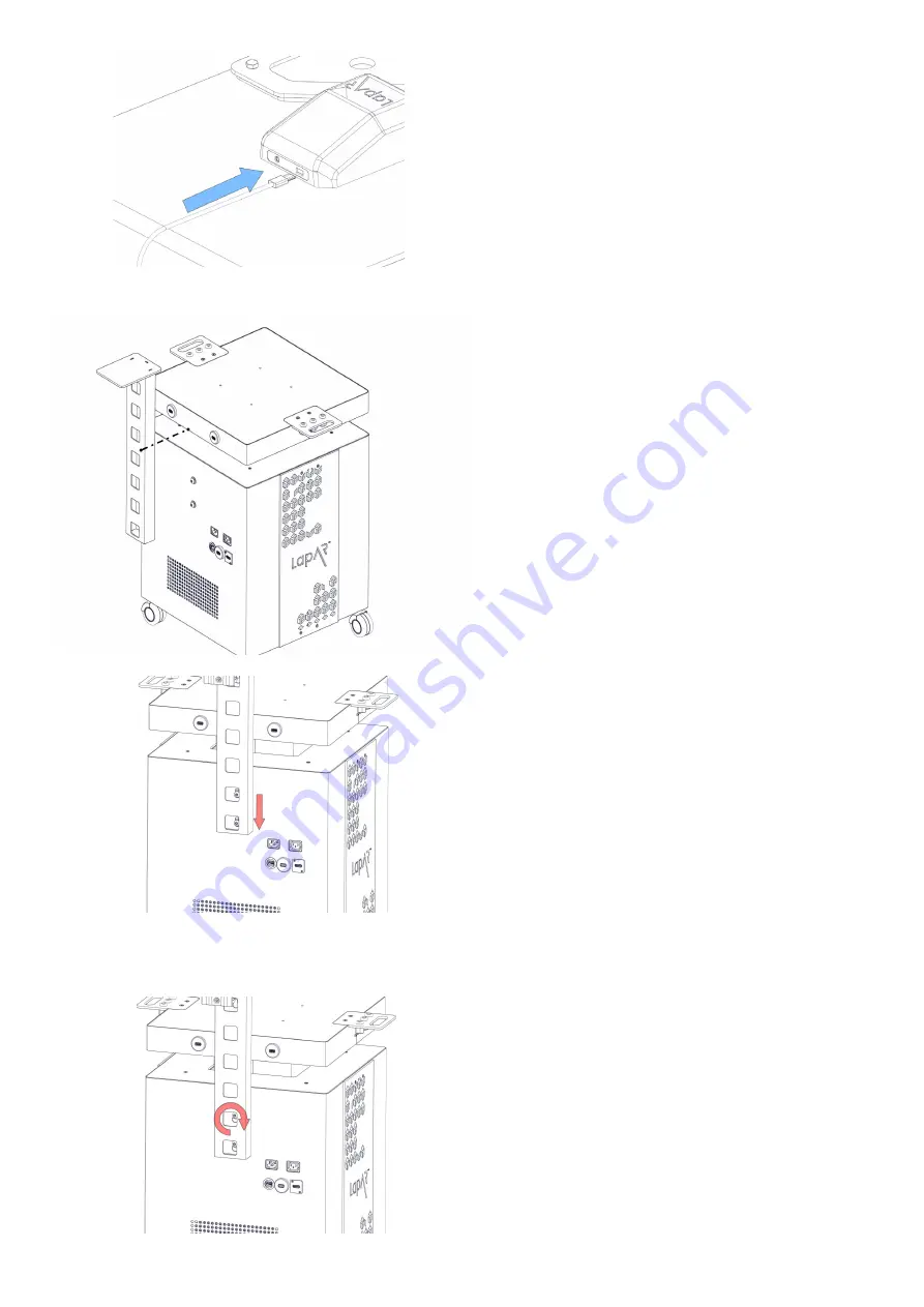
   Connect the USB micro into the back of the  

 camera. 

18 

|

   Start the assembly of your portable trolley  


system by unscrewing the M8 bolts at the 


rear of chassis so that you have around 3-4mm  


of space between the head of the bolt and    


the chassis wall. You can do this using the  


allen key provided. Take the L shaped screen    


bracket and place it onto the M8 bolts as  


shown.  

19 

|  

Drop the bracket onto the bolts. 

20 

|

   Screw the bolts tight using the allen key  


provided. Be careful not to overtighten at this  

 stage. 

Содержание Lapar Pro

Страница 1: ...a c c e s s i b l e a f f o r d a b l e f u n c t i o n a l Pro...

Страница 2: ...re flat surface 2 Now take the following parts MA01 x2 AR20_U02 x1 WN14 x2 M5B24 x2 Using the image as a guide pay close attention to the part orientation in this step or you will have to undo work at...

Страница 3: ...ssembly 7 At this stage the simulator should look exactly like the reference image If something appears to be incorrect go back through the steps again 8 Locate the following parts AR20_TPB01 x1 AR20_...

Страница 4: ...side to complete the assembly 10 Remove the AR20_CAM from its packaging and place into positon as shown 11 Take 2x M5B24 bolts and affix the AR20_ CAM into position DO NOT plug in at this stage 12 Tak...

Страница 5: ...important to note that the simulator is capable of multiple platform positions When inserting AR20_TAB you will most commonly use the angled base for Augmented Reality applications 13 Locate following...

Страница 6: ...f chassis so that you have around 3 4mm of space between the head of the bolt and the chassis wall You can do this using the allen key provided Take the L shaped screen bracket and place it onto the M...

Страница 7: ...the assembled monitor bracket and clamp it in position as shown 22 Screw the clamp until tight 23 Attach the monitor screen using the 4x M4 bolts provided 24 As shown in the image plug in the IEC HDMI...

Страница 8: ...te socket 27 Plug the IEC connector into the back of the system 28 Plug the connector into the mains power 25 Carefully thread the 3 wires we plugged in during the previous step up through the L shape...

Страница 9: ...ready assembled onto the top surface 31 Plug in the USB cable to the USB ports on the trolley system Note depending on the system you have purchased USB port location may vary 32 Turn the system on us...

Страница 10: ...s Inovus Ltd will not be liable under this limited warranty if its testing and examination show that the alleged defect or malfunction in the product does not exist or results from Failure to follow I...

Страница 11: ...ify you that we have received your returned item We will immediately notify you on the status of your refund after inspecting the item If your return is approved we will initiate a refund to your cred...

Страница 12: ...Designed and manufactured by a c c e s s i b l e a f f o r d a b l e f u n c t i o n a l E info inovus org T 44 0 1744 752 952 W www inovus org...

Отзывы: