Inovance MD38CAN2 Скачать руководство пользователя страница 1

User Guide
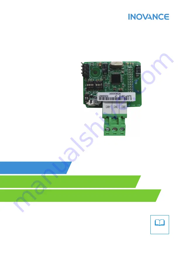
MD38CAN2 (CANopen) Card 

Optional Part for the MD Series Modular Vector AC Drive 

MD38CAN2 (CANopen) Car

d User Guide

Copyright   Shenzhen Inovance Technology Co., Ltd.

Shenzhen Inovance Technology Co., Ltd. 

Add.: Building E, Hongwei Industry Park, Liuxian Road, Baocheng No. 70 Zone, Bao

an District, Shenzhen 

Tel: +86-755-2979 9595

Fax: +86-755-2961 9897

Service Hotline: 400-777-1260

http: //www.inovance.com

Suzhou Inovance Technology Co., Ltd. 


Add.: No. 16 Youxiang Road, Yuexi Town, Wuzhong District, Suzhou 215104, P.R. China 

Tel: +86-512-6637 6666

Fax: +86-512-6285 6720

Service Hotline: 400-777-1260

http: //www.inovance.com

Min

A00

Data code 19010927

User Guide

Содержание MD38CAN2

Страница 1: ...User Guide MD38CAN2 CANopen Card Optional Part for the MD Series Modular Vector AC Drive Min A00 Data code 19010927 User Guide...

Страница 2: ...open Card Enabling 15 4 2 Parameters Related to Communication Control 15 4 3 Parameters Related to Communication Monitoring 16 4 4 Emergency Message and AC Drive Fault Description 19 5 Simple Diagnosi...

Страница 3: ...nication extension card specialized for CAN communication of the MD series AC drives It enables the AC drive to access the high speed CAN communication network and implements control of the field bus...

Страница 4: ...g figure Then fix the card with screws Note that the MD38CAN2 card cannot be inserted at power on Figure 2 1 Installation of the MD38CAN2 2 2 Hardware Layout The following figure shows the hardware la...

Страница 5: ...AC drive It is used to connect the card to the AC drive H Screw fixing hole It is used to fix the card with the M3 8 self taping screw CN1 Wiring terminal It is the CANopen bus wiring terminal LED Sta...

Страница 6: ...1 Note 2 Note 1 Select a CANlink interface card according to the PLC type Note 2 Select a CANlink interface card according to the AC drive type Figure 2 3 CAN bus connection NOTE Inovance s PLC and M...

Страница 7: ...relationship between the DIP switch states and the baud rates Table 2 4 Setting the baud rate for MD38CAN2 DIP Switch No Baud Rate 1 2 0 0 125 Kbps 0 1 250 Kbps 1 0 500 Kbps 1 1 1 Mbps CANopen device...

Страница 8: ...N Power on normal OFF Power on abnormal check whether the installation is correct ERR red ON Internal AC drive communication timeout Blinking quickly CANopen address setting incorrect Blinking twice C...

Страница 9: ...Nopen provides many types of communication objects COBs each having different features for details see the description of the CANopen standard protocol Different communication objects are used based o...

Страница 10: ...pping description of AC drive parameters The MD380 parameters are divided into three large groups groups F0 to FF groups A0 to AF and groups U0 to UF The following table lists the mapping addresses at...

Страница 11: ...meters at the read RAM operation can be used For example repeated rewriting of the RAM mapping address 0x2002 for F0 02 is allowed However the EEPROM mapping address 0x20F2 cannot be rewritten repeate...

Страница 12: ...on 11 bit ID 0x600 Node ID Node ID device address set by the DIP switch RTR 0 Remote frame flag 0 DATA0 Command code 0x40 0x40 read command DATA1 Low byte of index Parameter group F0 0xF0 DATA2 High b...

Страница 13: ...llowing table Table 3 6 SDO sending for write operation CAN CANopen Data Description 11 bit ID 0x600 Node ID Node ID device address set by the DIP switch RTR 0 Remote frame flag 0 DATA0 Command code 0...

Страница 14: ...ata 4 3 SDO failure error code Error Code Description Error Code Description 0x05040000 SDO access timeout 0x06070010 Data type not matched service parameter length not matched 0x06010000 Object acces...

Страница 15: ...FE 06 FE 07 RPDO3 FE 08 FE 09 FE 10 FE 11 Drivecom AC drive control command The command source is communication control that is F0 02 is set to 2 0001 Forward RUN 0002 Reverse RUN 0003 Forward jog 00...

Страница 16: ...atus AC drive running state Bit0 0 indicating stop and 1 indicating running Bit1 0 indicating forward RUN and 1 indicating reverse RUN Bit2 0 indicating no fault and 1 indicating AC drive fault Bit3 0...

Страница 17: ...l control 1 Terminal control 2 Communication control F0 03 Main frequency source X selection 9 Communication setting F0 04 Auxiliary frequency source Y selection Same as F0 03 Main frequency source X...

Страница 18: ...2 control 0x15 0 to 7FFF indicates 0 to 100 U3 21 FMP control 0x166 0 to 7FFF indicates 0 to 100 U3 22 Reserved Reserved Users cannot write this parameter U3 23 Rotation speed control 0x18 Signed valu...

Страница 19: ...ing running time 0x15 0 1 min U0 21 AI1 voltage before correction 0x16 0 001 V U0 22 AI2 voltage before correction 0x17 0 001 V U0 23 AI3 voltage before correction 0x18 0 001 V U0 24 Linear speed 0x19...

Страница 20: ...58 Z signal counting 0x3B 1 U0 59 Set frequency 0x3C 0 01 U0 60 Running frequency 0x3D 0 01 U0 61 AC drive state 0x3E 1 U0 62 Current fault code 0x3F 1 U0 63 Master sent data of point to point commun...

Страница 21: ...0 indicates communication error and 0xFF00 indicates the error specified by the manufacturer Error register For details see the data value of 1001H in the object dictionary described in the DS301 file...

Страница 22: ...al fault 0010 Communication abnormal 0011 Contactor abnormal 0012 Current detection fault 0013 Motor auto tuning fault 0014 Encoder PG card fault 0015 Parameter read write abnormal 0016 AC drive hardw...

Страница 23: ...or the configuration is incorrect In this case perform troubleshooting accordingly 5 3 Troubleshooting Check all nodes to see whether the baud rate and address configuration are consistent the DIP swi...

Страница 24: ...ally and different nodes can receive the same data This coding mode also features short transmission byte fast speed good fault tolerance and reliable data transmission making it suitable for industri...

Страница 25: ...heartbeat protocol and NMT message Based on the master slave communication mode NMT is used to manage and monitor all nodes in the network implementing node state control error control and node start...

Страница 26: ...x000 0 Command word Node ID Table 7 2 Command word of NMT Module ControlNMT message Command Word Description 0x01 Start Remote Node 0x02 Stop Remote Node 0x80 Enter Pre operational State 0x81 Reset No...

Страница 27: ...erational 127 Pre operational 7 3 Heartbeat Message A node can be configured to produce periodic messages called heartbeat message as described in Table 7 6 in which bit7 is 0 and bit6 to bit0 are the...

Страница 28: ...Revision History 26 Revision History Date Version Description December 2018 A00 First issue...

Страница 29: ...ers and secondary disasters c Hardware damage caused by dropping or transportation after procurement d Operations not following the user instructions e Damage out of the equipment for example external...

Страница 30: ...heng No 70 Zone Bao an District Shenzhen Tel 86 755 2979 9595 Fax 86 755 2961 9897 Service Hotline 400 777 1260 http www inovance com Suzhou Inovance Technology Co Ltd Add No 16 Youxiang Road Yuexi To...

Отзывы: