Innova S.r.l.
Pag. 11
N420227A_ManualeHRC_ Rev06.EN.docx
Fix the motor support in correspondence with the
drain hole by using screws and dowels (fig.8).
Fig.8 Attaching motor support
3. ELECTRICAL CONNECTIONS
3.1
GENERAL
'
-First starting any operation to make the electrical connection to make sure that the unit is not electrically supplied
-Perform electrical connections required exclusively by consulting the wiring diagram attached to this manual.
-Make that the electrical components selected for the installation (main switch, circuit breakers, cables and terminal section) are
suitable for
installed unit electrical power and taking into account the maximum achievable load. The data
related are indicated on the unit nameplate
-E 'forbidden to enter the electrical wiring in the unit except where specified in this booklet.
-Use cables and electrical conductors of appropriate sections and comply with current regulations of the various countries.
-Avoid absolutely to pass the electric cables in direct contact with pipes or components within the unit
3.2
CONNECTING
POWER
SUPPLY
AND
UNIT
CONTROL
-
S
VERSION
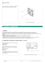
Connect to the power network the power supply
by the AC IN side.
-Blue wire (N)
-Brown wire (L)
Connect feeder towards the control unit the two
wires to the power supply output 12Vdc DC side
OUT.
Respect the polarity.
-Red wire (+)
-Black wire (-)
The command unit may be placed on the 503 box
or wall and has a fastening screw below for access
to internal parts.
Operating Voltage Connection and power supply


