


Section S - Item List
Page 42
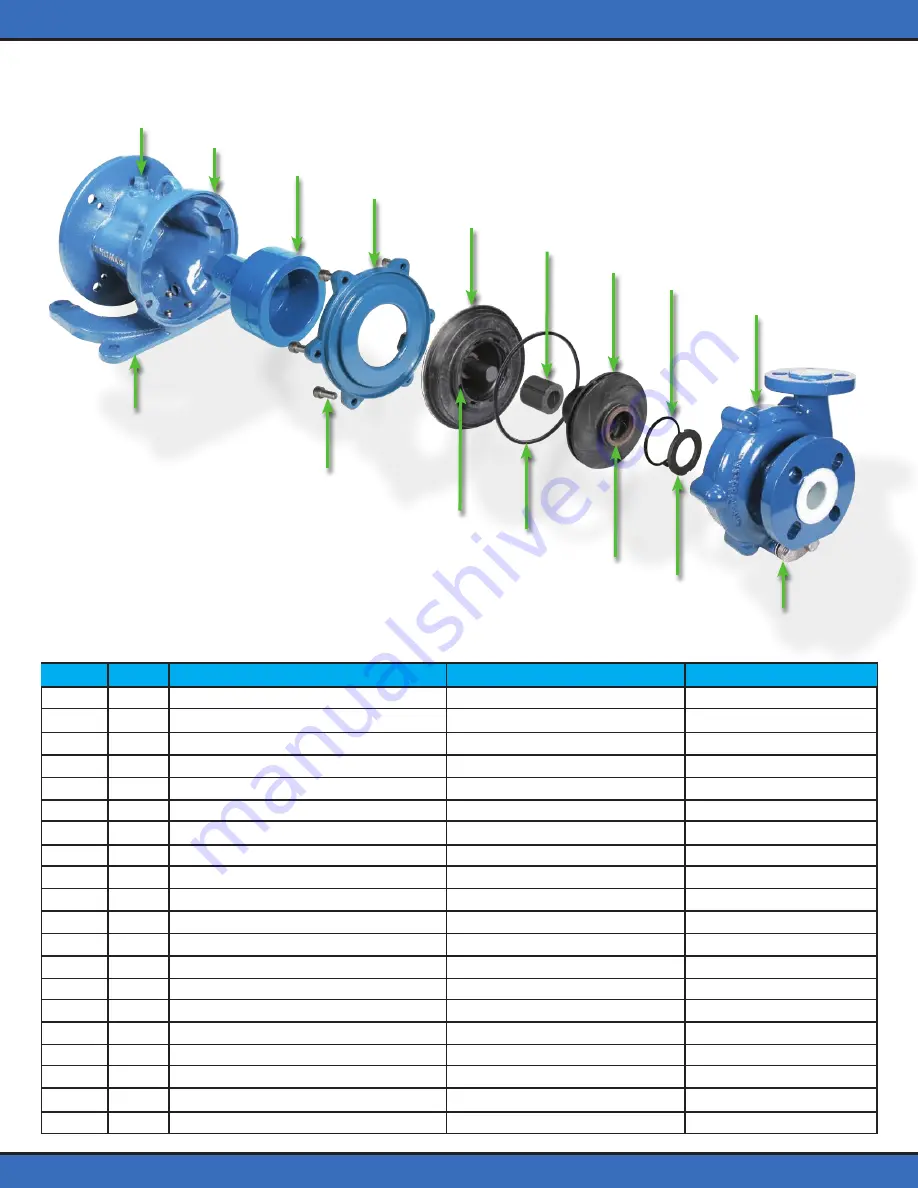
302
19
232
239
231
235
2
9
1
20
300
27
73
8
72
370 - 372
Casing
Impeller magnet Assembly
Wear Ring (Included w/ #2)
Retaining Ring
Adapter
Riser, Pump
Particulate Control Ring
Collar, Front Thrust
Gasket, O-Ring
Shell, Containment
Shaft (Included w/ #231)
Collar, Back Thrust (Included w/ #231)
Magnet Assembly, Outer
Bushing, Bearing
Ring, Containment
M10 Socket Cap Screw
Plug
Drain Flange
Drain Gasket
Drain Gasket Backing
1
2
8
9
19
20
27
72
73
231
232
235
239
300
302
370
371
372
1
1
1
1
1
1
1
1
1
1
1
1
1
1
1
10
1
1
1
1
Ductile Iron / ETFE Lining
CFR / ETFE
CFR / PTFE
CFR / ETFE
Ductile Iron
Ductile Iron
CFR / ETFE
Silicon Carbide
FEP / FKM Core
CFR / ETFE / Aramid Reinforced
Silicon Carbide
CF-PTFE
Ductile Iron / Neodymium Iron
Carbon Graphite
Ductile Iron
304 SS
304 SS
304 SS
PTFE
Neoprene
Ductile Iron / PFA Lining
PFA
Silicon Carbide
PFA
None
None
None
None
FKM (Fluorocarbon)
PFA / Aramid Reinforced
None
Silicon Carbide
None
Silicon Carbide
None
None
None
None
None
None
Item # Qty Part Name Standard Material Optional Material