6
IN3606 / IN3656 / IN3666 OPERATION MANUAL - REV. 1.1 11/27/99
©1998 - INLINE, INC.
ScantX
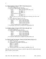
X=Scan Time between Channels (i.e. [SCANT12.5] would set the scan time to 12.5
seconds)
Possible allowable times are:
2.5 seconds
5.0 seconds
7.5 seconds
10.0 seconds
12.5 seconds
15.0 seconds
17.5 seconds
20.0 seconds
22.5 seconds
25.0 seconds
27.5 seconds
30.0 seconds
32.5 seconds
35.0 seconds
37.5 seconds
REMOTE CONTROL OPERATION
The IN3600 Series switchers have a REMOTE CONTROL port which allows these units to be remotely
controlled. Channels can be selected through the remote port by providing contact closures between the
appropriate pins. The port also includes a +5V power supply and tally outputs. Several contact closure
type control devices are available including:
IN3590 - An optional hard wired remote designed to work with IN3600 Series switchers.
IN6901 / IN6902 RS232 to Contact Closure Converters - allow IN3600 Series switchers and
other INLINE devices with contact closure control ports to be controlled by RS232 sources such
as control systems and computer serial ports.
Control System - many control systems are capable of providing contact closures.
Control Parameters
In order to select a channel, the channel select pin (pins 1 - 6) must be connected to Common (pin 7 or 8).
The contact closures may be momentary or continuous (latching).
Example: To switch to Input Channel #4, apply a contact closure between Pin 4 and Pin 7.
Tally Output
The REMOTE CONTROL port also provides tally outputs (pins 10 - 15) which may be used to trigger
other devices, provide feedback to a control system, or light indicator lights on a custom remote control
panel. When a channel is selected, either from the front panel or through the REMOTE CONTROL port,
the Tally Output for that channel is switched on. The Tally Output can switch voltages of up to 50 volts
and current up to 1.5 amps.
Control Port Pin Outs
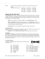
The REMOTE CONTROL port is a Female 15 Pin D connector with the
following pin outs:
Pin 1
Select Channel 1
Pin 9
+5 volts DC
Pin 2
Select Channel 2
Pin 10 *Tally output for Channel 6
Pin 3
Select Channel 3
Pin 11 *Tally output for Channel 5
Pin 4
Select Channel 4
Pin 12 Tally output for Channel 4
Pin 5
Select Channel 5
Pin 13 Tally output for Channel 3
Pin 6
Select Channel 6
Pin 14 Tally output for Channel 2
Pin 7
Common
Pin 15 Tally output for Channel 1
Pin 8
Common


