


2
IN3504/IN3506 OPERATION MANUAL - REV. 3.0 11/27/99
©1995-1999 - INLINE, INC.
INSTALLATION
This section offers step-by-step instructions for installing IN3500 Series switchers. A detailed
application drawing showing all equipment connections is included on the next page.
1. Connect all sources to the IN3504 / IN3506 input connectors. Unused inputs do not need to be
terminated.
IN3504 / IN3506: An interface may be required for each computer video signal source in order
to split off a signal for each local monitor, bring all signals into the RGBS format, and amplify
the signal to compensate for long input/output cable runs.
2. Connect the IN3504 / IN3506 output to the display device.
3. Apply AC power to the unit.
It is very important that all input / output connections be made utilizing high resolution coaxial cables.
Proper cable selection is critical to overall system performance, especially when working with high
frequency signals and/or long cable runs. The following cables are recommended for use with the
IN3504 / IN3506 switchers.
IN7000-4 Standard Resolution Coaxial Cables - 4 BNC Male to 4 BNC Male
IN7200-4 Ultra High Resolution Coaxial Cables - 4 BNC Male to 4 BNC Male
OPERATION
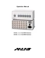
Power Switch
The POWER switch is located on the front panel and is a push, push again type switch which toggles
between OFF and ON each time the button is pressed. The red power LED will light to indicate that the
POWER switch has been activated and that an AC power source is available. The unit features Auto-
Power On, so once the POWER switch has been set to ON, the unit will be in that state if AC power is
removed and then reapplied to the unit.
Input Selection
The IN3504 / IN3506 switchers provide four or six front panel buttons which may be used to select the
desired input channel. Any time the unit is powered up, Input 1 is automatically selected. In order to
select a different input, press the corresponding input button and the appropriate green LED will light to
indicate the current active channel. All non-selected channels are terminated to 75 Ohms. The output
signal may be blanked (no input selected) by pressing and holding any two input buttons simultaneously.
Input channels may also be selected remotely by using an optional IN3590 wired remote or a control
system (see Remote Control Operation on page 4 for more details).
Since these switchers are passive they also bi-directional, meaning that signals may pass backwards
through the unit. In such an installation, a single source signal is hooked up to the OUTPUT connector
and multiple display devices are attached to the INPUT connectors. When an input is selected, the
source signal is routed to one of the attached display devices.