background image

Safety Instructions


I    03 

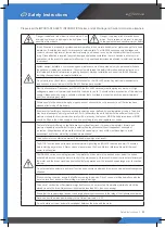
Safety Instructions

INJ-4500 series is intended for professional incorporation into comp lete equipment or systems as part of a fixed 

installation. If installed incorrectly it may present a safety hazard. The INJ-4500 series uses high voltages and 

currents, carries a high level of stored electrical energy, and is used to control mechanical plant that may cause 

injury. Close attention is required to system design and electrical installation to avoid hazards in either normal 

operation or in the event of equipment malfunction. Only qualified electricians are allowed to install and maintain 

this product.

System design, installation, commissioning and maintenance must be carried out only by personnel who have 

the necessary training and experience. They must carefully read this safety information and the instructions in 

this Guide and follow all information regarding transport, storage, installation and use of the INJ-4500 series, 

including the specified environmental limitations.

Do not perform any flash test or voltage withstand test on the INJ-4500 series. Any electrical measurements 

required should be carried out with the INJ-4500 series disconnected.

Electric shock hazard! Disconnect and ISOLATE the INJ-4500 series before attempting any work on it. High 

voltages are present at the terminals and within the drive for up to 10 minutes after disconnection of the electrical 

supply. Always ensure by using a suitable multimeter that no voltage is present on any drive power terminals 

prior to commencing any work.

Where supply to the drive is through a plug and socket connector, do not disconnect until 10 minutes have 

elapsed after turning off the supply.

Ensure correct earthing connections and cable selection as per defined by local legislation or codes. The drive 

may have a leakage current of greater than 3.5mA; furthermore the earth cable must be sufficient to carry the 

maximum supply fault current which normally will be limited by the fuses or MCB. Suitably rated fuses or MCB 

should be fitted in the mains supply to the drive, according to any local legislation or codes.

The level of integrity offered by the Optidrive control input functions – for example stop/start, forward and 

maximum speed is not sufficient for use in safety-critical applications without independent channels of 

protection. All applications where malfunction could cause injury or loss of life must be subject to a risk 

assessment and further protection provided where needed.

The driven motor can start at power up if the enable input signal is present.

The STOP function does not remove potentially lethal high voltages. ISOLATE the drive and wait 10 minutes 

before starting any work on it. Never carry out any work on the Drive, Motor or Motor cable whilst the input 

power is still applied.

The INJ-4500 series can be programmed to operate the driven motor at speeds above or below the speed 

achieved when connecting the motor directly to the mains supply. Obtain confirmation from the manufacturers of 

the motor and the driven machine about suitability for operation over the intended speed range prior to machine 

start up.

Do not activate the automatic ault reset function on any systems whereby this may cause a potentially dangerous 

situation.

When mounting the drive, ensure that sufficient cooling is provided. Do not carry out drilling operations with the 

drive in place, dust and swarf from drilling may lead to damage.

The entry of conductive or flammable foreign bodies should be prevented. Flammable material should not be 

placed close to the drive. Relative humidity must be less than 95% (non-condensing).

Ensure that the supply voltage, frequency and single phase input correspond to the rating of the Optidrive as delivered.

Never connect the mains power supply to the Output terminals U, V, W.

Do not install any type of automatic switchgear between the drive and the motor

Danger : Indicates a risk of electric shock, which, if not

avoided, could result in damage to the equipment and

possible injury or death.

Danger : Indicates a risk of electric shock, 

which, if not avoided, could result in damage 

to the equipment and possible injury or death.

Please read the IMPORTANT SAFETY INFORMATION below, and all Warning and Caution information elsewhere.

Содержание INJ-4500

Страница 1: ... Manual This manual describes how to use the S Drive has been developed by a small pump motor inverter Since applying the high reliability products PID algorithm be sure and get familiar with the operation manual before using ...

Страница 2: ...mp 4 Wiring Diagram 5 Sensor Connection Operation Method INJ 4500 Constant pressure control 6 INJ 4500 Display Set up LCD display Display color indications Setting the pressure 7 Multi connection 8 Sensor Error 8 Inverter Parameters 9 Booster Parameters 10 Alarm Log 3 4 5 6 7 8 9 10 11 12 13 14 15 Table of Contents An Alternative Answer to Perfect Water Pressure ...

Страница 3: ... fitted in the mains supply to the drive according to any local legislation or codes The level of integrity offered by the Optidrive control input functions for example stop start forward and maximum speed is not sufficient for use in safety critical applications without independent channels of protection All applications where malfunction could cause injury or loss of life must be subject to a ri...

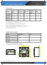
Страница 4: ...ature at rated current 40 C 104 F Grade of protection IP55 Weight indicated is without the packaging Model V in V Max V out V Max I out A Typical motor P2 kW Size INJ 45001 1 x 230 15 3 x 230 5 0 75 1 INJ 4500 1 x 230 15 3 x 230 8 1 5 1 INJ 4500 1 x 230 15 3 x 230 12 2 2 1 Model Weight Kg Size INJ 4500 2 4 1 INJ 4500 2 4 1 INJ 4500 2 4 1 1 2 3 4 120 130 13 8 8 5 120 130 2 4 127 2 1 8 2 3 5 2 0 3 1...

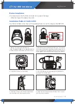
Страница 5: ...and not thrown away 3 Undo the 4 screws on the inverter 5 Bolt down the four inner holes located inside the drive down with the screws provided 2 Place the heat sink provided unto the motor Connect the motor wires to the inverter output lines Use the screws from the motor and bolt down the heatsink unto the motor Note The original gasket should be placed before placing the heatsink 4 Lift up the i...

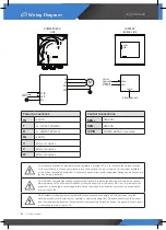
Страница 6: ... safe voltage levels Failure to observe this precaution could result in severe bodily injury or loss of life Only qualified electrical personnel familiar with the construction and operation of this equipment and the hazards involved should install adjust operate or service this equipment Read and understand this manual and other applicable manuals in their entirety before proceeding Failure to obs...

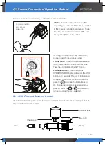
Страница 7: ...sing either the or and press the run button once the Hz is selected RU N STOP RU N STOP RUN STOP RU N Sensor connection and switching to automatic or manual operation Note The color of the sensor can differ depending on the brand The sensor indicated in this manual is a Keller brand sensor The left line of the sensor Brown color is SEN and the right line White color is SEN Pressure tank INJ 4500 P...

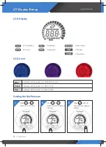
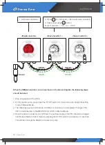
Страница 8: ... or button to set the desired pressure Press button to complete the pressure setting 1 2 3 Blue Indicates that the system is in OPERATION mode Purple Indicates that the system is in STOP mode Red Indicates that the system is in FAULT mode VFD Operation VFD Stop Parameter 1 Parameter 2 Sensor Alarm VFD Alarm Pump Alarm ...

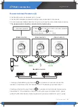
Страница 9: ...and shielded cable 0 5mm2 section must make the communication between devices 1 Setting up theMASTER pump Press the for a duration of 2 seconds and see if the indication arrow on the right hand side indicates AUTOMATIC OPERATION The Master pump should state 1 2 Setting up the SLAVE pump Press the for a duration of 2 seconds and see if the indication arrow on the right hand side indicates MULTI CON...

Страница 10: ...step 2 is completed Change of the VFD s interconnected to the MASTER from AUTO to Manual Mode 4 Once the sensor connection is confirmed the next lead pump 2nd VFD should be changed from Manual Mode to AUTO mode by pressing the STOP button for a duration of 3 seconds This will then change the Master to the second pump 1 Automatic operation 2 Press for 2 seconds confirm automatic operation 3 Check o...

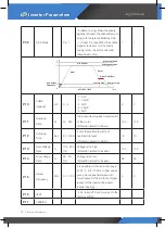
Страница 11: ... 3 220 Middle Point Voltage Mid point Voltage can be directly set by the user This function makes the VFD operate with the quadratic characteristic This setting value must be equal to or greater than Mini Output Freq and eaqul to or less than Max voltage Freq 110 120 P 05 Min Frequency Hz 0 1 20 Minimum Motor Frequency 1 5 1 5 P 06 Min Voltage V 3 100 Minimum Motor Voltage 15 15 P 07 ACC Time Sec ...

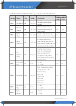
Страница 12: ... 9 It sets the maintaining time of overload trip level Protection related to Motor 10 10 P 13 Over Voltage Rate 100 200 Voltage is too high Protection related to Inverter 120 120 P 14 Low Voltage Rate 50 90 Voltage is too low Protection related to Inverter 60 60 P 15 Carrier Frequency KHz 3 0 15 0 It is possible to choose in the range of 2 5 4 6 8 10 kHz Higher values give a more sinusoidal wave w...

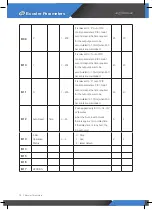
Страница 13: ...ssure gauge differs from the pressure sensor please adjust the sensor value with this paremeter 0 0 B 04 Low Pressure setting Bar 0 2 2 0 To set the lowest pressure Note Once the default set pressure is adjusted the Low Pressure setting will be automatically adjusted to 20 of the set pressure 0 3 0 5 B 05 Low Pressure Stop Sec 0 or 1 0 OFF 1 1 999 20 20 B 06 Low Current Amp 0 5 5 0 Note This value...

Страница 14: ...tput power to be accumulated to 1 0 Hz when 200 bar errors are maintained 40 40 B 11 D 1 200 It is relevant to D out of PID control parameters PID I Gain 1 second means the time required for the output power to be accumulated to 1 0 Hz when 200 bar errors are maintained 40 40 B 12 Auto Reset Time 0 20 It can applied only for OC OL OV LV faculties when the Auto reset occures there is approx 1min de...

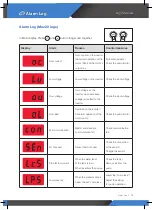
Страница 15: ...Check the input voltage Over load Overload on the inverter Abnormal operation of the motor pump Check the pump motor Fail communication Master and slave are communication fail Check communication line Err of sensor Sensor fail to connect Check the connection of the sensor Change the sensor Stop for low current When the water level of the tank is low When air enters the pumps Check the tank Remove ...

Страница 16: ...16 I NJ 4500L http www injungtech com 82 0 31 357 8655 ...

Отзывы: