2
IPS24140
La spia luminosa
4
segnala la presenza
della tensione di rete ed il corretto funzio-
namento dell’apparecchio.
La tensione di uscita può essere prelevata
o dai morsetti
5
(+V,-V), o dal connettore
6
(+V, -V); sul connettore
6
è inoltre
possibile prelevare un segnale di man-
canza rete elettrica (FAULT: 5V = Rete
Ok, 0V = No Rete) ed è disponibile un in-
gresso per la connessione di una sonda
termica alloggiata in centrale (RTH, utiliz-
zato SOLTANTO da centrali INIM, NON
UTILIZZARE).
Utilizzo con centrali rivelazione incendio
Nel caso di utilizzo del presente apparato
in abbinamento con centrali di rivelazione
incendio tutte le segnalazioni obbligatorie
di stato e di guasto devono essere previste
e rese disponibili in centrale.
La connessione delle batterie deve essere
realizzata mediante un opportuno disposi-
tivo di sezionamento che garantisca il
funzionamento dell’alimentatore anche in
caso di corto circuito delle batterie.
The LED
4
indicates the presence of the
mains voltage on the input terminals and
the proper working order of the device.
The output voltage can be taken from ter-
minals
5
(+V, -V), or from the connector
strip
6
(+V, -V) which also provides a fault
output for mains fault signals (FAULT: 5V
= Mains OK; 0V = No Mains).
DO NOT USE the connector marked RTH ,
as it is suitable for use with INIM control
panels ONLY).
Use with fire control panels
If you use this device with fire control panels
all obligatory status and fault signalling
must be provided for, and made available.
An automatic isolating device must be used
for the battery connection; this will allow
the power supply unit to function properly in
the event of batteryshort-circuit.
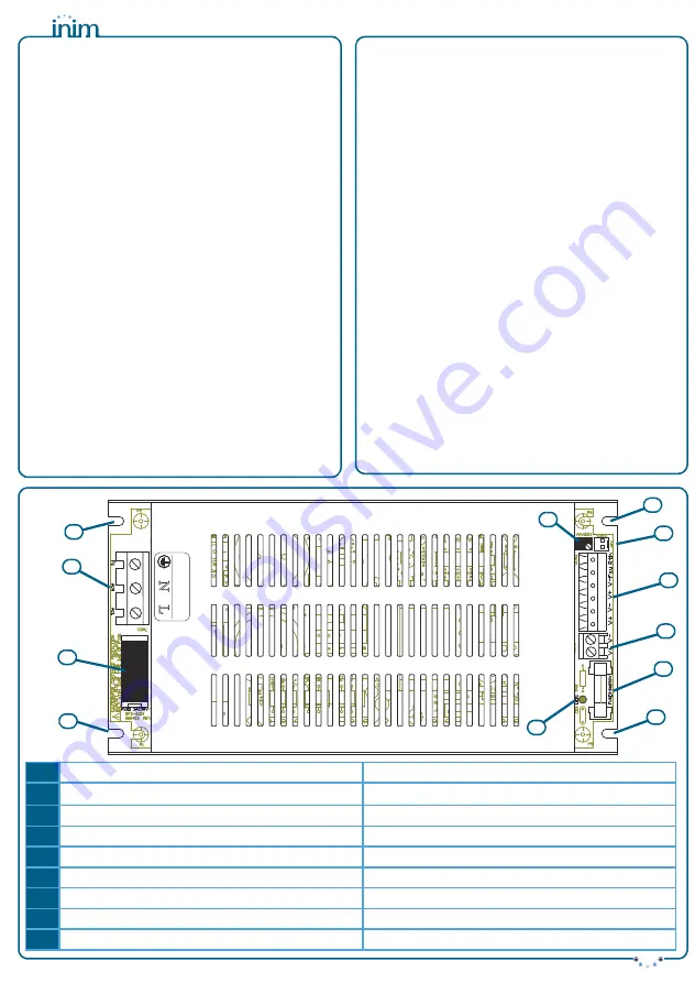
1
Morsettiera ingresso rete
Mains input terminals
2
Foro di fissaggio
3,25mm
Mounting holes
3.25mm
3
Trimmer
Trimmer
4
Spia luminosa
LED indicator
5
Morsettiera uscita
Output terminals
6
Connettore uscita
Output connector
7
Connettore per sonda termica
Thermal probe connector
8
Fusibile d’ingresso (F1) F 3,15A 250V
Input protection fuse (F1) F 3.15A 250V
9
Fusibile d’uscita (F2) F 8A 250V
Output protection fuse (F2) F 8A 250V
N
L
230V ~ 50/60 Hz
AC
Input
8
4
3
7
6
5
2
9
Fig.1
2
2
2
1
I
I


