background image

2

WARNING SYMBOL IDENTIFICATION

Always wear eye protection

when operating or perform-

ing maintenance on this tool.

WARNING

WARNING

Always wear hearing

protection when operating

this tool.

Read this manual before

operating tool.

WARNING

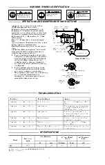
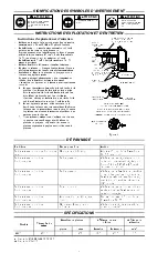
OPERATIONS AND MAINTENANCE INSTRUCTIONS

Always use clean, dry air at 90 psig (6.2 bar/

620 kPa) maximum at the tool inlet.

Lubrication -- Inject approximately 1.5 cc of

Powerforce No. 50 Oil into the air inlet before

starting the tool and after each two or three hours

of operation, unless the air line lubricator is used.

Lubricate with 1.5 cc of Powerforce No. 50 Oil

before storage.

Use a 3/8” (10 mm) inside diameter air supply

hose.

Speed Adjustment -- Rotate regulator (7) to adjust

from no rotation to maximum speed.

Installing/Removing sanding pad and sandpaper

discs:

Always turn off the air supply and disconnect the

air supply hose before installing, removing, or

adjusting any accessory on the tool.

1. For pad installation, have the lock tab in the

lock position (See Figure 1). For lock position,

align hole in spindle with lock tab. Press lock

tab into hole. Hand tighten the pad in a

clockwise direction. After pad installation,

unlock the lock tab for orbital action sanding

(See Figure 1).

2. For pad removal, align hole in spindle with

lock tab. Press lock tab into hole. Rotate the

pad counter clockwise to remove the pad.

3. When applying a sandpaper disc to the sanding

pad, a disc with adhesive backing is

recommended. Align sandpaper on pad and

press self adhesive paper onto pad.
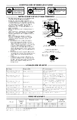
MAIN LINES 3 TIMES

AIR TOOL INLET SIZE

TO

AIR

SYSTEM

TO

AIR

TOOL

LUBRICATOR

REGULATOR

FILTER

BRANCH LINE 2 TIMES

AIR TOOL INLET SIZE

DRAIN REGULARLY

COMPRESSOR

(Dwg. TPD905--1)

Lock tab

Install pad with tool

in LOCK position

Insert lock tab into drive cylinder hole

UNLOCK for orbital action

view from

underside of

tool

Figure 1

Drive cylinder

TROUBLESHOOTING

Problem

Possible Cause

Action

Low speed or tool will not function

Lac

k of lubrication

Add 1.5 cc of Powerforce oil #50 to

the tool

Low speed or tool will not function Low pressure

Ensure system regulators are set

properly to have 90 psi (6.2 bar/

620 kPa) at the tool inlet.

Low speed or tool will not function Low pressure

Ensure proper hose size. Long

hose lengths may require a hose

with a 1/2” ID or larger

Low speed or tool will not function System leakage

Ensure connections are tight and

hoses are not damaged

Low speed or tool will not function Debris build up in tool

Flush tool with 1.5 cc of Power-

force oil #50

Low speed or tool will not function Regulator (7) in wrong position

Ensure that the regulator is in the

proper position

SPECIFICATIONS

Model

Free Speed

rpm

Pad Diameter

H Sound Level

dB (A)

z

Vibrations

Level

Model

rpm

In

mm

Pressure

Power

m/s

2

PF100

12000

6

152

87.3

100.3

6.3

H Tested in accordance with PNEUROP PN8NTC1.2

z Tested to ISO8662

Содержание POWERFORCE PF100

Страница 1: ...released Check for excessive speed and vibration before operating Air powered tools can vibrate in use Vibration repetitive motions or uncomfortable positions may be harmful to your hands and arms Stop using any tool if discomfort tingling feeling or pain occurs Seek medical advice before resuming use Use accessories recommended for the Powerforce by Ingersoll Rand These Sanders will operate at th...

Страница 2: ...nter clockwise to remove the pad 3 When applying a sandpaper disc to the sanding pad a disc with adhesive backing is recommended Align sandpaper on pad and press self adhesive paper onto pad MAIN LINES 3 TIMES AIR TOOL INLET SIZE TO AIR SYSTEM TO AIR TOOL LUBRICATOR REGULATOR FILTER BRANCH LINE 2 TIMES AIR TOOL INLET SIZE DRAIN REGULARLY COMPRESSOR Dwg TPD905 1 Lock tab Install pad with tool in LO...

Страница 3: ... to which this declaration relates is in compliance with the provisions of Directives By using the following Principle Standards Serial No Range D Vose Patrick Livingston Name and signature of authorised persons Name and signature of authorised persons Date Date SAVE THESE INSTRUCTIONS DO NOT DESTROY When the life of the tool has expired it is recommended that the tool be disassembled degreased an...

Страница 4: ...ier que la vitesse et les vibrations ne sont pas excessives avant d utiliser l outil Les outils pneumatiques peuvent vibrer pendant l exploitation Les vibrations les mouvements répétitifs et les positions inconfortables peuvent causer des douleurs dans les mains et les bras N utiliser plus d outils en cas d inconfort de picotements ou de douleurs Consulter un médecin avant de recommencer à utilise...

Страница 5: ...de papier de verre à support adhésif sur le plateau de ponçage Aligner le disque sur le plateau et presser le papier auto collant sur le plateau TUYAUTERIE PRINCIPALE AU MOINS 3 FOIS LA DIMEN SION DE L ADMISSION D AIR DE L OUTIL VERS LE RÉSEAU D AIR COMPRIMÉ VERS L OUTIL PNEU MATIQUE LUBRIFICATEUR RÉGULATEUR FILTRE LIGNE SECONDAIRE AU MOINS 2 FOIS LA DIMEN SION DE L ADMISSION D AIR DE L OUTIL VIDA...

Страница 6: ...rtificat est conforme aux prescriptions des Directives en observant les normes de principe suivantes No Serie D Vose Patrick Livingston Nom et signature des chargés de pouvoir Nom et signature des chargés de pouvoir Date Date NOTE CONSERVEZ SOIGNEUSEMENT CES INSTRUCTIONS NE PAS LES DÉTRUIRE A la fin de sa durée de vie il est recommandé de démonter l outil de dégraisser les pièces et de les séparer...

Страница 7: ...utilización El eje de la herramienta podría seguir girando brevemente después de haber soltado la palanca de estrangulación Compruebe si hay exceso de velocidad o vibración antes de usar Las herramientas neumáticas pueden vibrar durante el uso La vibración repetición o posiciones incomodas pueden dañarle los brazos y manos En caso de incomodidad sensación de hormigueo o dolor deje de usar la herra...

Страница 8: ...izar un disco con papel protector adhesivo Alinee el papel de lija en el disco y haga presión sobre el papel adhesivo para que se adhiera al disco TUBERÍAS PRINCIPALES 3 VECES EL TAMAÑO DE ENTRADA DE HERRAMIENTA NEUMÁTICA A SISTEMA NEUMÁTICO A HERRA MIENTA NEUMÁTICA LUBRICADOR REGULADOR FILTRO TUBERÍA DE RAMAL 2 VECES EL TAMAÑO DE ENTRADA DE HERRAMIENTA NEUMÁTICA PURGAR PERIÓDICAMENTE COMPRESOR es...

Страница 9: ...os que se refiere la presente declaración cumplen con todo lo establecido en las directivas conforme a los siguientes estándares Gama de No de Serie D Vose Patrick Livingston Nombre y firma de las personas autorizadas Nombre y firma de las personas autorizadas Fecha Fecha NOTA GUARDE ESTAS INSTRUCCIONES NO DESTRUYA Una vez vencida la vida útil de herramienta se recomienda desarmar la herramienta d...

Страница 10: ...toll free in the U S 1 866 207 6923 Please provide the following information Model Number Part number as shown in parts list TP1896 15 16 17 19 18 6 14 12 10 11 13 4 3 2 8 7 9 5 1 1 Lever Kit includes PF100 RHK1 11 O ring 2 Lever 12 Spring 3 Lever Screw 13 O ring 4 Nut 14 Screw 5 Regulator Kit includes PF100 RK1 15 Sanding Pad PF100 825 6 6 Retaining Ring 16 Tool Label PF100 300 7 Regulator 17 War...

Страница 11: ...11 ...

Страница 12: ......

Отзывы: