


30
18-CD37D1-2-EN
Installer’s Guide
the secondary recuperative cell. Remove the larger drain line
(from the secondary cell) and trim to fit between the secondary
cell and the new trap location. On upflow units, plug the hole in
the blower deck where the tube went through.
Remove the hose from the induced blower and reposition into
the other drain tap of the inducer, which is located 90° clock-
wise around the inducer. Move the cap from that drain tap to
the unused drain tap. On upflow units, plug the hole in the
blower deck where the tube went through. This tube on down-
flow units will need to be cut to fit between the inducer and
the trap. On upflow units, this tube may need to be extended,
using the tubing shipped with the furnace.
Connections must be made to an
OPEN/VENTED DRAIN
.
Outdoor draining of the furnace and coil condensate is permis-
sible if allowed by local codes. Caution should be taken to
prevent drains from freezing or causing slippery conditions that
could lead to personal injury. Excessive draining of conden-
sate may cause saturated ground conditions that may result in
damage to plants.
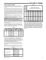
NOTE: Use 1/2" or larger PVC or CPVC pipe and fittings as
required for drain connections (fittings, pipe and solvent
cement not provided).
NOTE: A corrosion resistant condensate pump must be
used if a pump is required for a specific drain system.
IMPORTANT:
The condensate drain should be installed with
provisions to prevent winter freeze-up of the condensate drain
line. Frozen condensate will block drains, resulting in fur nace
shutdown. If the drain line cannot be installed in a conditioned
space, then UL listed heat tape should be applied as required
to prevent freezing (per manufacturer’s instructions). The heat
tape should be rated at 5 or 6 watts per foot at 120 volts. Self-
regulating (preferred) or thermostatically controlled heat tape
is required.
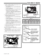
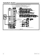
Figure 51. DOWNFLOW (VERTICAL)
Left
side
Use CPVC tubing from Trap outlet,
over burner box to cabinet exit
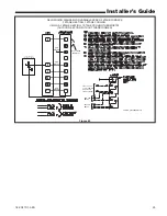
Figure 52. DOWNFLOW (VERTICAL)
Right
side
Cut off curved end of
Inducer drain hose
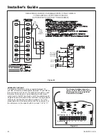
Figure 53. DOWNFLOW (HORIZONTAL)


