


(Dwg. MHP2644)
NOTICE
•
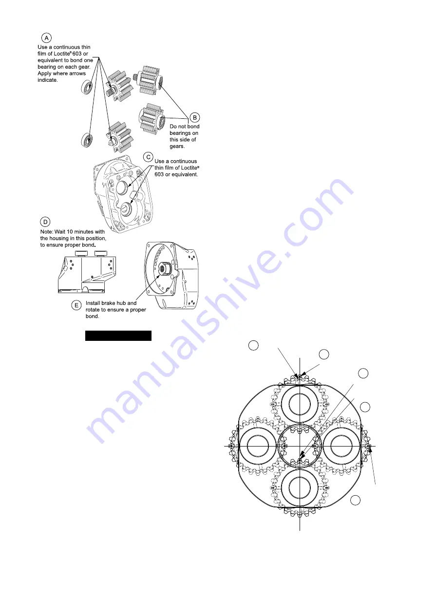
Before following instructions A and C on Dwg. MHP2644 place Loctite®
“Activator” 7649 on all gear axles and holes in housing gears go through.
For Motor without Emergency Stop and Overload
1. Install gasket (91) on motor cover (83).
2. Install cover (92) and secure with capscrews (34). Refer to “TORQUE CHART”
on page 19 for torque requirements.
3. If pendant adapter plate (605) or (613) or rope control block (313) or (405) was
removed from motor cover (83), refer to pendant assemblies for installation.
For Motor with Emergency Stop and Overload
Refer to Dwgs. MHP3037 and MHP3038.
1. Lubricate and install ‘O’ ring (201) and seal (189) on base plate (199).
2. Lubricate and install ‘O’ ring (197) to plunger (198).
3. Install diaphragm (196), washer (195) with stop nut (194) on plunger (198) and
insert into base plate (199). Ensure plunger assembly moves freely in bore of
base plate.
4. Insert base plate (199) with plunger into motor cover (83).
5. Lubricate and install ‘O’ rings (204) on valve seat (205).
6. Place washer (206), diaphragm (212), cap (211), seal (203), sleeve (209) and
washers (206) and (208) onto capscrew (62) and insert into valve seat (205). Apply
a thin film of Loctite® 243 or equivalent to capscrew threads. Do not over tighten
capscrew.
7. Place seal (210) and cap (202) on capscrew (62). Place spring (213) on cap (202).
8. Install valve seat assembly into end cover (183).
9. Lubricate and install ‘O’ ring (191) on regulating screw (192), insert into
emergency stop end cover (183) avoiding damage to the ‘O’ ring. Secure with
screw (102). Install screw with Loctite® 243 or equivalent.
10. Lubricate and install spring (193).
11. Install ‘O’ rings (187) to valve seat (186).
12. Insert axle (188) into valve seat (186) then install seals (189) on each end of axle
(188).
13. Insert valve seat (186) into emergency stop end cover (183).
14. Insert ball (47) into emergency stop end cover (183).
15. Install gasket (91) on motor cover (83).
16. Install emergency stop end cover (183) on motor cover (83) with capscrews (103).
Refer to “TORQUE CHART” on page 19 for torque requirements.
17. Insert plug (182) if removed during disassembly.
18. Install setscrew (180) in emergency stop end cover (183).
19. If pendant adapter plate (605) was removed from motor cover (83), refer to
pendant assemblies for installation.
n
Hoist Disc Brake Assembly
Refer to Dwgs. MHP2999 and MHP3038.
1. Lubricate and install ‘O’ ring (6) on brake housing (61).
2. Lubricate and install ‘O’ rings (64) and (6) on piston (63). Press piston assembly
in brake housing (61). Internal ‘O’ ring (64) must enter brake housing first. Avoid
damaging ‘O’ rings.
3. Install plates in brake housing (61) in the following order: Friction plate without
clips (66) then drive plate (67) then friction plate with clips (72) then drive plate
(67). Repeat this plate sequence finishing with a friction plate with clips (72).
Align drive plate slots with slots in splined hub (65).
4. Install splined hub (65).
5. Install reaction plate (68) into brake housing (61).
6. Align holes and install gasket (7) on brake housing (61).
7. Ensure retainer ring (10) is installed on spline of drive gear (80).
8. Install springs (69) in motor housing (76).
9. Carefully install assembled brake in motor housing (61) and secure with
capscrews (62). Install capscrews (62) with Loctite® 243 or equivalent. Splined
hub must locate on motor drive gear (80) and remain engaged in drive plates.
Refer to “TORQUE CHART” on page 19 for torque requirements. For a correct
assembly the brake housing must be completely inside the motor housing.
10. Install plug (1) and washer (151) in brake housing.
11. Mount motor and brake assembly on end cover (73) with washers (75) and
capscrews (74).
n
Hoist Reduction Gear Assembly
Refer to Dwg. MHP3165.
1. Lubricate and install ‘O’ rings (6) and (138) and bearing (137) in reduction gear
end cover (5).
2. Assemble planet support assembly (341). Install bearings (147), internal bearing
rings (141), needle bearings (142) and (144), spacers (146) and rings (148) in four
planetary gears (140). Install planetary gear assemblies into planetary carrier (17).
Ensure that planetary gears (140) are installed with the smaller gear head
diameter nearest the ring gear (19).
3. Align planetary gear assemblies with small holes in planetary carrier and install
planet axles (16).
4. Time planet gears as shown in Dwg. MHP3049 on page 12, A. Aligned Teeth;
B. Timing Mark; C. Offset Teeth and Timing Mark. Use the sun gear (153) to
maintain timing position.
5. Install bearings (11) in planetary carrier (17) and retainer ring (14) on sun gear
(153).
6. With sun gear (153) still in place, install planetary assembly in ring gear (19)
carefully remove sun gear (153) without removing planetary assembly and place
ring gear flat on surface with planetary assembly facing up.
7. Align gears with ring gear (23) and install over planetary assembly and ring gear.
8. Install assembled sun gear (152) in primary gear assembly (126).
9. Install assembled primary gear assembly (126) on planet housing (17).
10. Install bearing (132) on primary gear assembly (126) with three drops of
Loctite® 603 on external ring of bearing.
11. Install pinion shaft (25) through reduction gear housing assembly so it locates
in the sun gear of primary gear assembly.
12. Lubricate and install ‘O’ ring (6) in reduction gear end cover (5).
13. Align capscrew holes and install reduction gear end cover (5) on ring gear (23).
14. Install ‘O’ ring (64) on muffler assembly (88) and thread muffler assembly into
reduction gear end cover (5).
15. Install capscrews (4) and lockwashers (44) through reduction gear assembly
parts.
Aligned Teeth
Aligned Teeth
Timing Mark
Timing Mark
Offset Teeth
and Timing
Mark
A
A
C
B
B
(Dwg. MHP3049)
n
Powerhead Assembly
Refer to Dwg. MHP3165.
1. Lubricate and install ‘O’ ring (6) on hoist body (36)
12
Form MHD56473 Edition 2
Содержание LC2A060S
Страница 16: ...SERVICE NOTES 16 Form MHD56473 Edition 2...
Страница 17: ...SERVICE NOTES Form MHD56473 Edition 2 17...
Страница 18: ...SERVICE NOTES 18 Form MHD56473 Edition 2...
Страница 20: ...R www ingersollrandproducts com...