MAINTENANCE
WARNING
•
Never perform maintenance on hoist while it is supporting a load.
•
Before performing maintenance, tag controls:
•
Only allow personnel trained in operation and service of this hoist to
perform maintenance.
•
After performing any maintenance on hoist dynamically test hoist to 100%
of its rated capacity, in accordance with ASME B30.16 standards, before
returning hoist to service. Testing to more than 100% of rated capacity may
be required to comply with standards and regulations set forth in areas
outside the USA.
•
Shut off air system and depressurize air lines before performing any
maintenance.
Proper use, inspections and maintenance increase the life and usefulness of your
Ingersoll Rand equipment. During assembly, lubricate gears, nuts, capscrews and
all machined threads with applicable lubricants. Use of antiseize compound and/or
thread lubricant on capscrew and nut threaded areas prevents corrosion and allows
for easy disassembly of components.
n
Maintenance Intervals
The Maintenance Interval Chart below is based on intermittent operation of
equipment for eight hours each day, five days per week. If equipment is in operation
for more than eight hours a day or is operated in severe applications or
environments, more frequent maintenance should be performed.
Interval
Maintenance Check
Start of each shift
Make a thorough visual inspection of hoist for damage.
Do not operate hoist if damage is found.
Operate in both directions. Hoist must operate smoothly
without sticking, binding or abnormal noises.
Check operation of pendant control and brake.
Semiannually
Inspect disc brake friction linings and sprag clutch
assembly. Clean or replace parts as required.
Yearly
Inspect hoist gearing, shafts and bearings for damage or
wear. Repair or replace as necessary.
Check all of supporting members, including trolley if
used. Repair or replace as required.
n
Disc Brake Adjustment
No disc brake adjustment is required. If brake fails to hold load, brake must be
disassembled, inspected, repaired and tested prior to placing hoist in service. When
any part of friction disc thickness measures 0.072 in. (1.83 mm) or less, or if oil groove
pattern is not clearly visible, friction discs must be replaced.
n
Load Chain Replacement
n
Load Chain Weld Placement
It is suggested that a short length of 32 mm load chain be available when replacing
hoist load chain. Feeding a short length of load chain through bottom block
assembly or power head assembly prior to installing new load chain may simplify
installation.
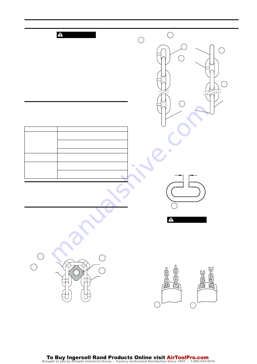
Weld on perpendicular load chain must always face away from sheaves. Refer to
Dwg. MHP0042 on page 5, A. Load Chain; B. Standing Link; C. Load Sheave; D.
Chain Weld.
Load Chain
Standing Link
Load Sheave
Chain Weld
A
B
C
D
(Dwg. MHP0042)
n
Replacement Load Chain Link Arrangement
Correct load chain installation requires that load chain have either an even or odd
number of total chain links. Refer to Dwg. MHP2336 on page 5 for illustration of
how to determine chain arrangement; A. Chain Link (View From Motor); B. 25-50-100
Ton Hoist; C. First Link; D. Chain Weld; E. End Link; F. 75 Ton Hoist Only; G. Chain
Weld Located on Back Side.
First
Link
End
Link
Chain
Weld
Chain
Weld
located
on back
side
25–50–100
Ton
Hoists
75
Ton
Hoist
Only
Chain Link
(view facing Motor)
A
B
C
E
D
F
G
(Dwg. MHP2336)
n
Load Chain ‘C’ Link
Load chain replacement for all hoist models can be accomplished efficiently and
easily by using existing load chain to install new load chain.
1. Using an abrasive wheel, cut a section from end link of existing chain to form a
‘C’ link. Refer to Dwg. MHP2337 on page 5, A. ‘C’ Link.
2. Connect new chain to old chain by inserting end of new chain into ‘C’ link. Make
certain welds and links on new chain match positioning of welds and links on
chain being replaced. For model-specific information, refer to the appropriate
hoist model diagram.
1.378 in.
(35 mm)
“C” Link
A
(Dwg. MHP2337)
CAUTION
•
Do not distort link in any manner. The link must be able to pass over chain
sheaves without binding.
n
Determining Twisted, Kinked or ‘Capsized’ Load Chain
Ensure chain is not twisted, kinked or ‘capsized’ during installation. Refer to Dwg.
MHP0020 on page 5, A. Appearance of Chain Not Twisted; B. Appearance of Chain
Twisted; and Dwg. MHP0043 on page 6, A. Make certain the bottom block has
NOT been flipped through the chain falls.
Twisted Chain
A
Appearance of
Chain Not Twisted
Appearance of
Chain Twisted
B
(Dwg. MHP0020)
Capsized Chain
Form MHD56243 Edition 4
5
Содержание HA3-075
Страница 12: ...R www ingersollrandproducts com...


