
A.
If the cylinder is installed, refer to step 10 for IC core removal
instructions.
B.
Using a thin flat screw driver, turn the action bar slot clockwise
(cw) until it stops at about 11:00.
C.
Then turn the action bar counterclockwise (ccw) to the 7:00 posi-
tion.
There is no physical stop at this location.
D.
Using the control key, insert IC core into the lever and spindle.
E.
Remove control key.
F.
Operate key to test for proper operation.
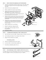
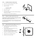
STEP 15
TIMING INSTRUCTIONS FOR IC CYLINDER LOCKS
For The Following Functions: RU371, RU381, RU561, RU571
STEP 16
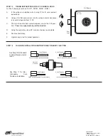
TAILPIECE INSTALLATION INSTRUCTIONS FOR RU381 FUNCTION
See Step 13 for Standard
Cylinder Tailpiece Instal-
lation
See Step 11 for Inter-
changeable Core
Tail-piece Installation.
RH Shown
Action
bar slot
Door
edge
Long Tailpiece
Short Tailpiece
Outer Standard Cylinder Assembly
Inner Standard Cylinder Assembly
Clutch on
Outside
Long Tailpiece
Short Tailpiece
Outer Interchangeable Core Assembly
Inner Interchangeable Core Assembly
800-266-4456
©
2008 Schlage Lock Company
Printed in Country
031534-000-70 Rev. 04/08-b