04584355_ed3
5
Troubleshooting Guide
Trouble
Probable Cause
Solution
Low power
Dirty Inlet Bushing or Inlet Screen and/or Muffler Using a suitable cleaning solution, in a well ventilated area, clean
Inlet Screen, Inlet Bushing and Muffler.
Worn or broken Vanes
Replace complete set of Vanes.
Worn or broken Cylinder and/or scored End
Plates
Examine Cylinder and replace it if it is worn or broken or if bore is
scored or wavy. Replace End Plates if they are
scored.
Dirty motor parts
Disassemble tool and clean all parts with a suitable cleaning
solution, in a well-ventilated area. Reassemble tool as instructed
in this manual.
Motor will not run
Improper positioning of the Reverse Valve Lever
or Reverse
Valve
Make certain that the Reverse Valve Lever is in the reverse
position or one of the three forward positions. If the tool has
been disassembled, refer to Dwg. TPD2024-1 for proper Reverse
Valve and Reverse Lever orientation.
Incorrect assembly of motor
Disassemble motor and replace worn or broken parts and
reassemble as instructed.
Tool will not impact
Insufficient lubricant in the impact mechanism
Remove Hammer Case Assembly and lubricate impact
mechanism.
Broken or worn impact mechanism parts
Remove Hammer Case Assembly and examine impact
mechanism parts. Replace any worn or broken parts.
Impact mechanism not assembled correctly
Refer to Assembly of Impact Mechanism.
Related Documentation
For additional information refer to:
Product Safety Information Manual 04580916.
Product Information Manual 16573206.
Parts Information Manual 04584579.
Manuals can be downloaded from ingersollrandproducts.com
Assembly of the Tool
1. Wipe a thin film of the recommended grease on the inside of
the Hammer Case Bushing (42) and insert the assembled impact
mechanism into the Hammer Case (43).
2. Secure the Hammer Case and impact mechanism by the anvil
(square drive) end in leather-covered or coppercovered vise jaws.
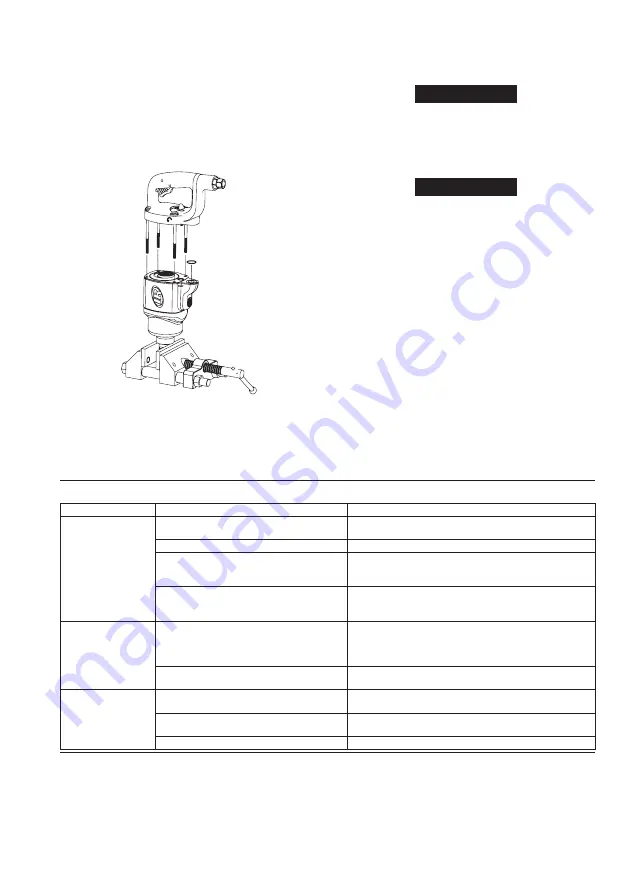
See Dwg. TPD2021-1.
(Dwg. TPD2021-1)
3. Install a new Hammer Case Gasket (41) on the Hammer Case
making sure that the holes in the gasket align with the holes in
the Hammer Case.
NOTICE
When installing optional Hanger Kit, place Gasket on the
Hammer Case followed by the Hanger.
4. Wipe a small amount of the recommended grease on the flat side
of the Hammer Frame Washer (36) and place it on the splined
face of the Hammer Frame (37) with the hub end of the washer
pointing up.
NOTICE
When installing optional Hanger Kit, place additional washer
provided between the Hammer Frame and Hammer Frame
Washer.
5. Set the fully assembled Motor Housing over the opening in the
Hammer Case. Insert the spline drive of the Rotor into the splined
hole of the impact mechanism. Make sure of the wide section of
the Hammer Case is just above the Trigger.
6. Place a new Handle Gasket (19) over the rear of the Housing
making sure that the holes in the Gasket align with the holes
in the Housing and that the profile of the Gaskets matches the
profile of the Housing.
7. Place a Motor Clamp Washer (20) over the rear of the motor with
the convex side up and matching the large outside diameter of
the Rear End Plate.
8. Place O-ring (32) in counterbore around air passage on the
housing.
9. Place the Handle (1) over the back of the Housing making sure
that the Reverse Valve Lever (8) is in the full-forward (clockwise)
position with the lugs in the Lever engaging the slots in the
Reverse Valve. Make sure that the index mark on the Reverse
Valve lines up with the index mark on the reverse valve bushing.
10. Install the four Backcap Bolts and tighten to 10-12 ft-lbs
(13-16 Nm) torque.
Содержание 2925B2Ti
Страница 6: ...Notes...
Страница 7: ...Notes...
Страница 8: ...ingersollrandproducts com 2014 Ingersoll Rand...


