background image

SPECIFICATIONS

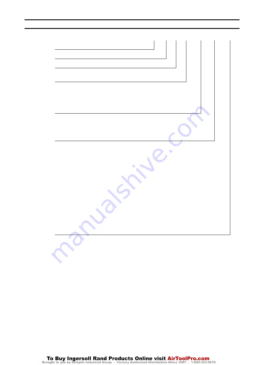
Model Code Explanation:


Example: FA150KGiMR12–1–C-E


FA

150KGi

MR

12

-

1

-

C

-

E


Series:


FA

= Force 5 Infinity Air Powered


Capacity (based on wire rope at full drum):


150KGi

= 330 lb [150 kg] Man Rider Rating


Man Rider

 Designation:


MR

Man Rider


Drum Length:


8

= 8 inches (203 mm)


12

= 12 inches (305 mm) (standard)


16

= 16 inches (406 mm)


24

= 24 inches (610 mm)


Drum Brake:


Manual Drum Band Brake Standard


A

= Automatic drum band brake


Control:


1

= Winch mounted lever throttle (Standard)


3XX

= Remote control (Contact factory) †


Wire Rope Take-off Range:


0°- 90°

Wire rope take-off angle (standard).

 Contact factory for non-standard wire rope angles.


Design Temperature:


Blank

= 0° C (32° F) or warmer


C

= -20° C (-4° F)


Options:


7

= Grooved drum (Wire rope sizes in sixteenths, e.g. 7/16 in)


B

= Winch mounted base


E

= Emergency lowering system


F

= Air Line Accessories (mounted on front or back of winch guard panel)


H

= Stainless Steel Hoses (rubber hose is standard)


J

= Air Line Accessories


K

= Stowage valve


M1

= Typical Material Certificates (2.2) *


M2

= As-received traceability *


M3

= As-shipped traceability *


N1

= Type approval – ABS ††


N2

= Type approval – DNV ††


Q

= Special Paint ††


W1

= ABS – witness testing ††


W2

= DNV – witness testing ††


W3

= LRS – witness testing ††


W4

= Customer witness testing ††


X

= Testing ††


-E

=

Compliance with EU Machinery Directive, refer to “DECLARATION OF CONFORMITY” on page 15 (Includes emergency stop and overload

protection)


Notes:


Refer to ‘Traceability’ on page 4 for a description of the differences between M1, M2 and M3.


† Not covered in this manual.


†† If N, Q, W or X are entered, the details must be specified in the text of the sales order.


Form MHD56314 Edition 4

3

Содержание FORCE 5i Man Rider FA Series

Страница 1: ...Product Information Model FA150KGi Dwg MHP2738 Save These Instructions Form MHD56314 Edition 4 January 2011 71456206 2011 Ingersoll Rand Company...

Страница 2: ...rom the externally mounted piston air motor is transmitted through a coupling and shaft to the planetary reduction gear assembly The output from the planetary reduction gear assembly is connected to t...

Страница 3: ...drum Wire rope sizes in sixteenths e g 7 16 in B Winch mounted base E Emergency lowering system F Air Line Accessories mounted on front or back of winch guard panel H Stainless Steel Hoses rubber hose...

Страница 4: ...tificates according to EN 10204 Ex DIN 50049 3 1b on load bearing parts Conformity documents affirm by a department independent of the manufacturing department that the actual parts used in the produc...

Страница 5: ...2 inch NPT inlet Exceeding 90 psi 6 3 bar 630 kPa may cause inadvertent activation of the overload device If air supply varies from what is recommended winch performance will change Install air line l...

Страница 6: ...itude regarding safety It is the operator s responsibility to refuse to operate the winch under unsafe conditions 1 Lifting and lowering speeds are operator controlled and should be as slow as practic...

Страница 7: ...Line Detector CAUTION Slack line detector and limit switch functions are not operable when emergency release valve is activated Refer to Dwg MHP2739 If slack line exists between winch and sheave slac...

Страница 8: ...erly Inspection should be conducted by an Ingersoll Rand trained Inspector every 90 days and a record of the inspection maintained n Daily Inspection Complete inspections prior to start of daily tasks...

Страница 9: ...y Limit Switch Product equipped with a rotary limit switch must be stored with the limit switch not activated LUBRICATION To ensure continued satisfactory operation of winch all points requiring lubri...

Страница 10: ...de 6 to 9 drops per minute at maximum motor speed n Wire Rope Follow wire rope manufacturer s instructions At a minimum observe the following guidelines 1 Clean with a brush or steam to remove dirt ro...

Страница 11: ...bricator Air In Filter A B C D E Dwg MHP0191 Dwg MHP2760 B Wire Rope Anchor A Dead End of Wire Rope Dwg MHP2753 Fill Breather Plug Motor Case Level Plug Position Drain Plug Position A B C D Dwg MHP227...

Страница 12: ...GRAPHICS CONTINUED Haul in Payout Lift Slider Handle UP to Unlock A C B Dwg MHP2976 Drum Reduction Gear Assembly Fill Plug Position Drain Plug Inboard Upright A D E B C Dwg MHP2297 Dwg MHP2688 12 Form...

Страница 13: ...h Motor Winch Control Valve Shut off Valve Main Air Source Stop On Haul in Payout Emergency Brake Release Air Source Slack Line Limit Switch Payout Limit Switch Haul in Limit Switch Pilot Valve A B C...

Страница 14: ...SERVICE NOTES 14 Form MHD56314 Edition 4...

Страница 15: ...l ring vedr rer overholder bestemmelserne i f lgende direktiv er DE auf das sich diese Erkl rung bezieht der folgenden Richtlinie entspricht EL ES a los que se refiere la presente declaraci n cumplen...

Страница 16: ...www ingersollrandproducts com...

Отзывы: